SG4 BASE
27/73
4 ELECTRICAL CONNECTIONS
4.1 PIN-OUT AND CONFIGURATION PIN CONNECTION
4.1.1 MODELS SG4-xx-xxx-OO-X
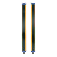
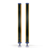
All electrical connections to the emitting and receiving units are made through a male M12 connector, located on
the lower part of the two units.
For receiver a M12 5-poles connector is used, while for emitter a M12 4-poles connector is used.
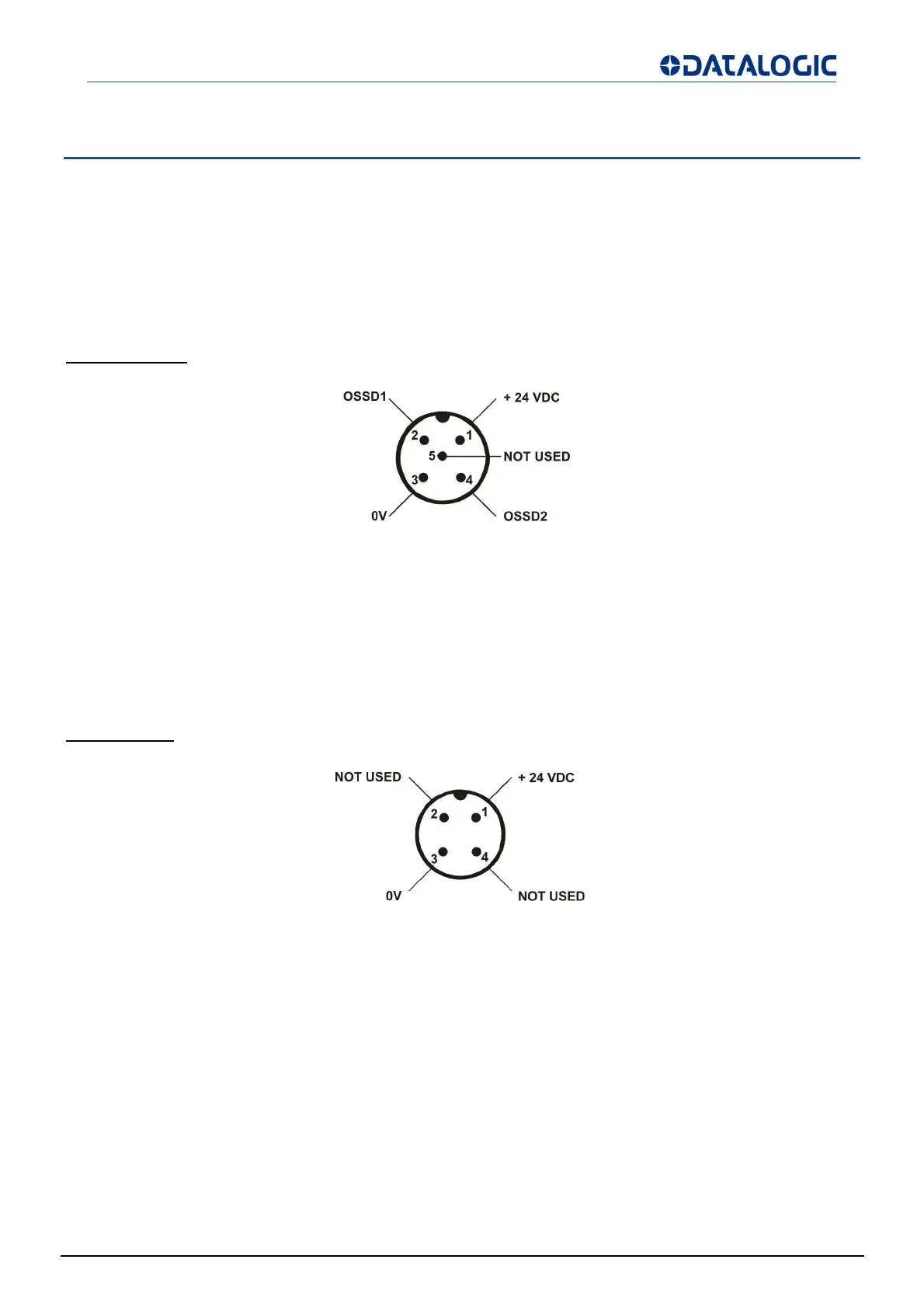
RECEIVER (RX):
Fig 25 - Receive
1 = brown = +24 VDC
2 = white = OSSD1
3 = blue = 0 V
4 = black = OSSD2
5 =
re
= NOT USED
EMITTER (TX):
Fig 26 - Emitte
1 = brown = +24 VDC
2 = white = NOT USED
3 = blue = 0 V
4 = black = NOT USED