SG4 BASE
30/73
4.2 NOTES ON CONNECTIONS
For the correct operation of the safety light curtains, the following precautions regarding the electrical connections
have to be respected:
• Do not place connection cables in contact with or near high-voltage cables and/or cable undergoing high
current variations (e.g. motor power supplies, inverters, etc.).
• Do not connect in the same multi-pole cable the OSSD wires of different light curtains.
Only fori SG4-xx-xxx-OO-E models:
• The TEST wire must be connected through a N.O. button to the supply voltage of the ESPE.
• The RESET/RESTART wire must be connected through a N.O. button to the supply voltage of the ESPE.
• The device is already equipped with internal overvoltage and overcurrent suppression devices.
• The use of other external components is not recommended.
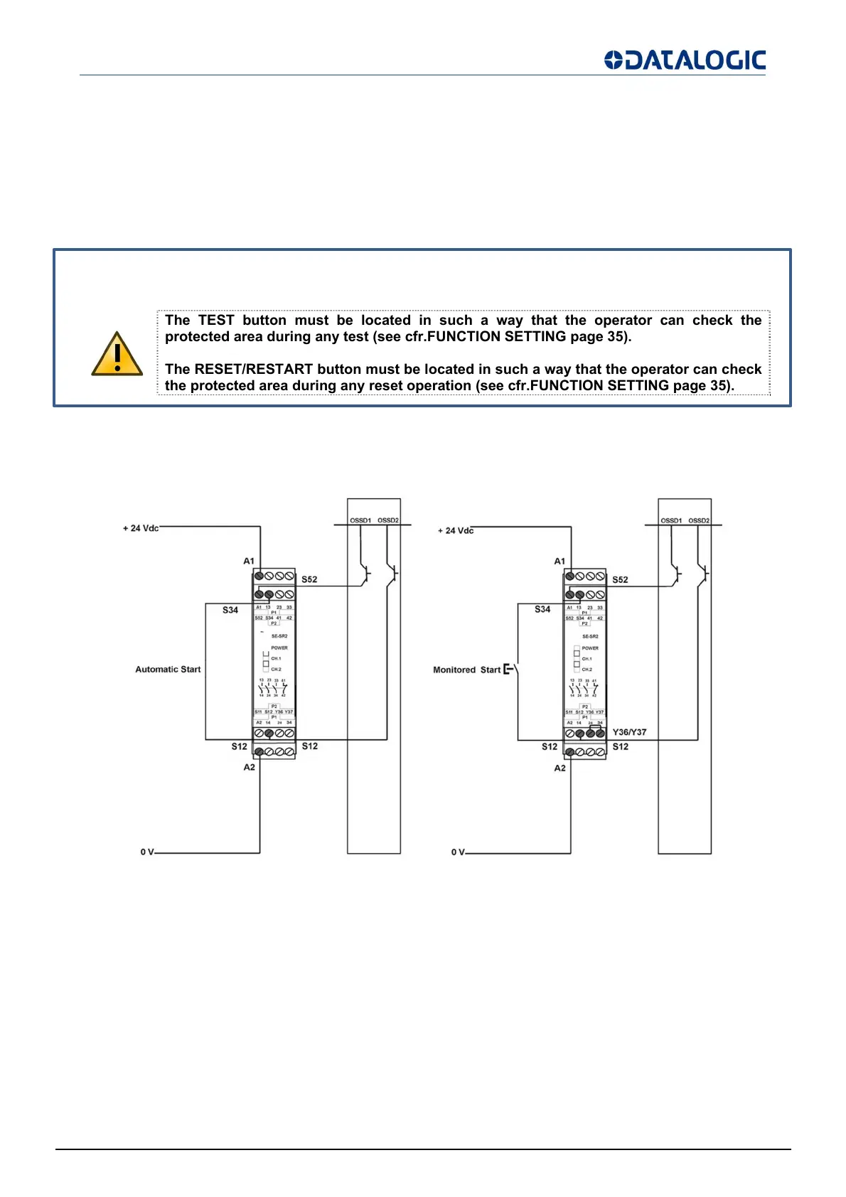
Example: connection to the safety relay SE-SR2
Fig 29 - Connection to SE-SR2 Safety Relais
The figures show the connection between the safety light curtains and the safety relay of the SE-SR2 series
functioning in the Automatic Restart mode (left side) and Manual Restart with monitoring (right side).
• Do not use varistors, RC circuits or LEDs in parallel at relay inputs or in series at OSSD outputs.
• The OSSD1 and OSSD2 safety contacts cannot be connected in series or in parallel, but can be used
separately, conforming to the plant’s safety requirements.
• If one of these configurations is erroneously used, the device enters into the output failure condition (see
cfr.USER INTERFACE AND DIAGNOSTICS page 41).
The TEST button must be located in such a way that the operator can check the
protected area during any test (see cfr.FUNCTION SETTING page 35).
The RESET/RESTART button must be located in such a way that the operator can check
the protected area durin
an
reset operation
see cfr.FUNCTION SETTING pa
e 35
.