SG4 BASE
28/73
4.1.2 MODELS SG4-xx-xxx-OO-E
All electrical connections to the emitting and receiving units are made through a male M12 connector, located on
the lower part of the two units.
For receiver a M12 8-pole connector is used, while for emitter a M12 4-pole connector is used.
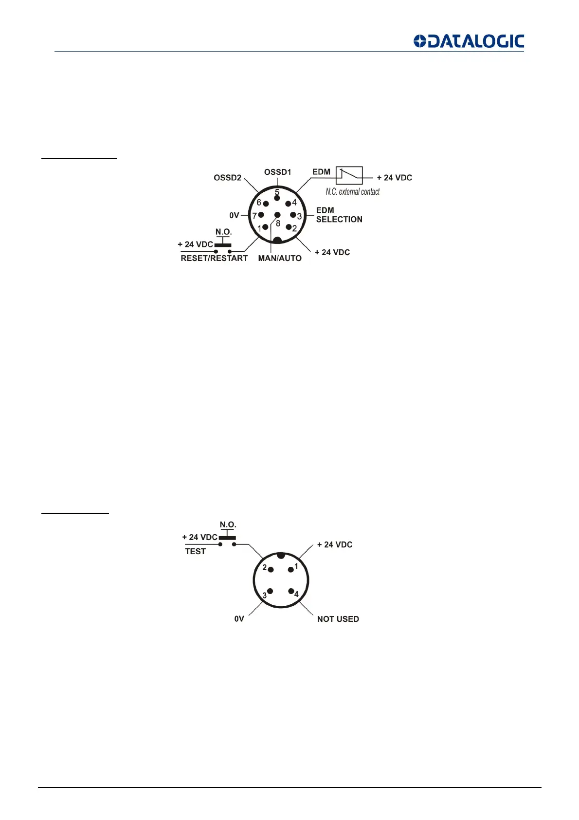
RECEIVER (RX):
Fig 27 - Receive
1 = white = RESET/RESTART
*
2 = brown = +24 VDC
3 =
reen = EDM SELECTION
4 =
ellow = EDM
5 =
re
= OSSD1
6 = pink = OSSD2
7 = blue = 0 V
8 = red = MANUAL/AUTOMATIC RESTART
(*) automatic RESTART --> RESET function
manual RESTART --> RESET / RESTART function
To set manual restart, connect Pin 8 (MAN/AUTO) with Pin 6 (OSSD2).
To set automatic restart, connect Pin 8 (MAN/AUTO) with Pin 5 (OSSD1).
To deactivate EDM function, connect Rx Pin 3 to 24VDC on Receiver.
EMITTER (TX):
Fig 28 - Emitte
1 = brown = +24 VDC
2 = white = TEST
3 = blue = 0 V
4 = black = NOT USED