14: Maintenance
PRC1099A-MS 14-7
14.3.3 Board Removal and Replacement
This section provides procedures for removing each board in the PRC1099A.
Remove and
Replace the
1650 kHz IF
Board
To remove and replace the 1650 kHz IF board:
1. Disassemble radio chassis (refer to “Chassis Disassembly” on page
14-4).
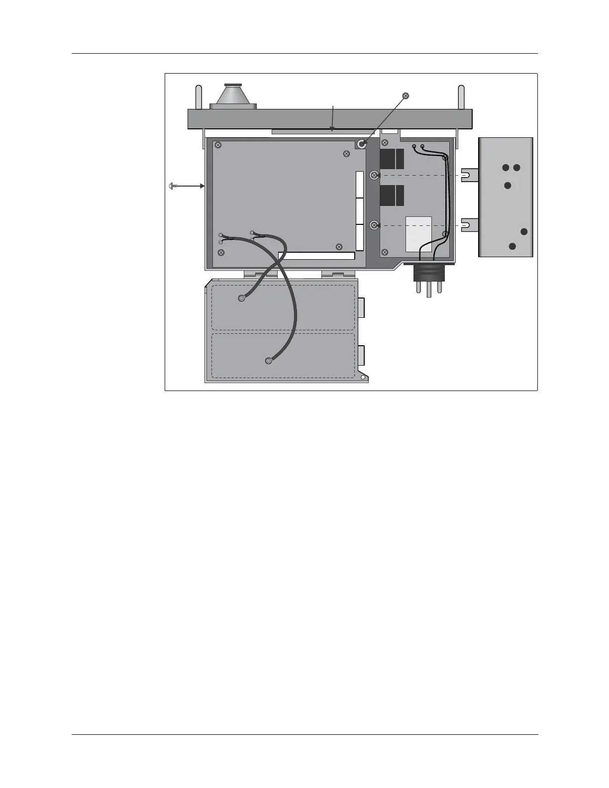
2. Remove the two side retaining screws (refer to Figure 14-6 above) to
release the PA module and Antenna Tuner module tray, and lift the tray
off the Audio/Filter board.
This makes it easier to remove the J1, J2 J3, and J4 connectors as well
as the two retaining screws discussed in step 4.
3. Disconnect RF coax connectors J2, J3, and J4. Disconnect
multiple-pin power connector J1.
4. Loosen (do not remove) the two retaining screws on the center plate
next to the Audio/Filter board. These screws may be obscured by
wiring harnesses from the Audio/Filter board.
5. Tilt the module up and slide it off these screws.
6. Reverse this procedure to install the new 1650 kHz IF board.
Figure 14-6 Board Locations (Bottom)
PA Module
Antenna Tuner
Module
Audio Filter
Board
J4
J5
J6