14: Maintenance
PRC1099A-MS 14-23
14.7 Adjustments
This section provides the adjustment point descriptions and locations on each
board.
14.7.1 Audio/Filter Board
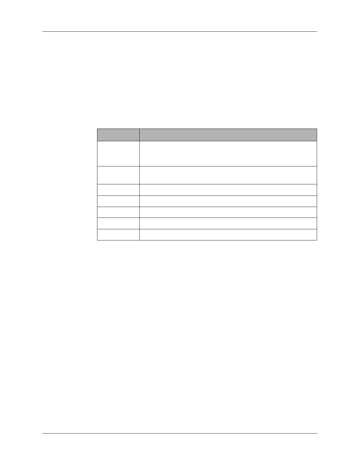
Table 14-4 below provides the adjustments included on the Audio/RF filter
board. Figure 14-7 on page 14-24 provides adjustment component locations
with adjustments and signal input/outputs indicated.
Table 14-4 Adjustment Potentiometers
Designator Adjustment
R12 Adjusts the squelch setting; at the factory, this is generally set for
the lowest setting that permits squelch to open as an incoming
signal is swept through passband.
R50 Adjusts carrier balance—factory set for minimum RF output in a
keyed, unmodulated condition.
R83 Sets transmit output to 20W in high power mode.
R82 Sets transmit output to 5W in low power mode.
R65 Sets CW tone oscillator frequency.
R24 Sets voice detect trip point.
R107 Sets contrast level of the Display board.