73
can be used as an input for the VLG’s. An exclamation mark ( ! ) can be put in front of the operand in order to invert
its logic state, for example !1D01 will be Active if 1D01 is Normal.
7 – CONTROLLED OUTPUT
Outputs to be controlled (on/off) based on the state of this input. The two output types allowed are relays (both
physical and virtual) and SNMP SETs. For the relays, adding a P suffix will Pulse the relay (ex: 1R01P), L will Latch
it and R will Release it.
8 – DELAY BEFORE ACTION
Delay before the input changes into an active state when an out-of-limit condition occurs. Prevents glitches from
setting-off any alarms.
9 – DELAY BEFORE RETURN TO NORMAL
Delay before the input returns to a normal state once an out-of-limit condition is over. Prevents too-brief returns-to-
normal from causing multiple repeated alarms.
10 – ENABLE
Enable / disable the input. Useful to deactivate an input, without losing all its settings, when the input is causing
intermittent problems or nuisance alarms.
11 – SYSTEM LOG
Log the input’s activity in the System Log. Useful when inputs do not need to be logged, but are required for day-
to-day operation.
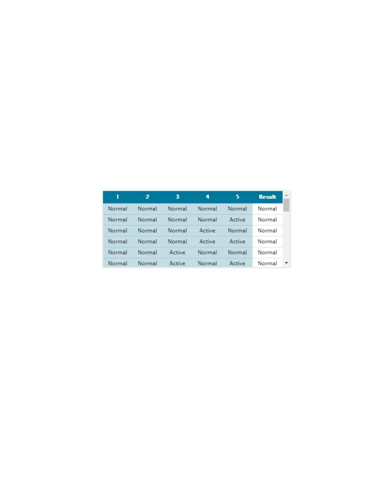
12 – TRUTH TABLE
Dynamic table showing the logic state (Result) of the VLG for every possible condition of its operands (1 to 5).
Normal is comparable to a logic low or logic 0, while Active is comparable to a logic high or logic 1.
13 – SIGNALLING ON – ALARM
Enables / disables alarming. When checked, any out-of-limit condition will automatically generate an alarm. When
unchecked, no alarm will be triggered when an out-of-limit condition occurs.
14 - SIGNALLING ON – RETURN TO NORMAL
Enables / disables Return To Normal signalling. When checked, a notification will be generated when the input
changes back to its normal state after an out-of-limit alarm condition. When unchecked, no notification will be sent
when the initial alarm condition returns to normal.
15 – REFRESH / READ
Refresh / read the screen content.
16 – SAVE / WRITE
Save the screen content.
17 – EXIT
Exit menu.