EasyManuals Logo

DayTronic 4000 Series User Manual

DayTronic 4000 Series
72 pages
To Next Page IconTo Next Page
To Previous Page IconTo Previous Page
Page #63 background imageLoading...
Page #63 background image
time t
3
, when a yet higher input value is detected, and the channel
begins once more to track the input upwards to a yet higher peak
(P
2
).
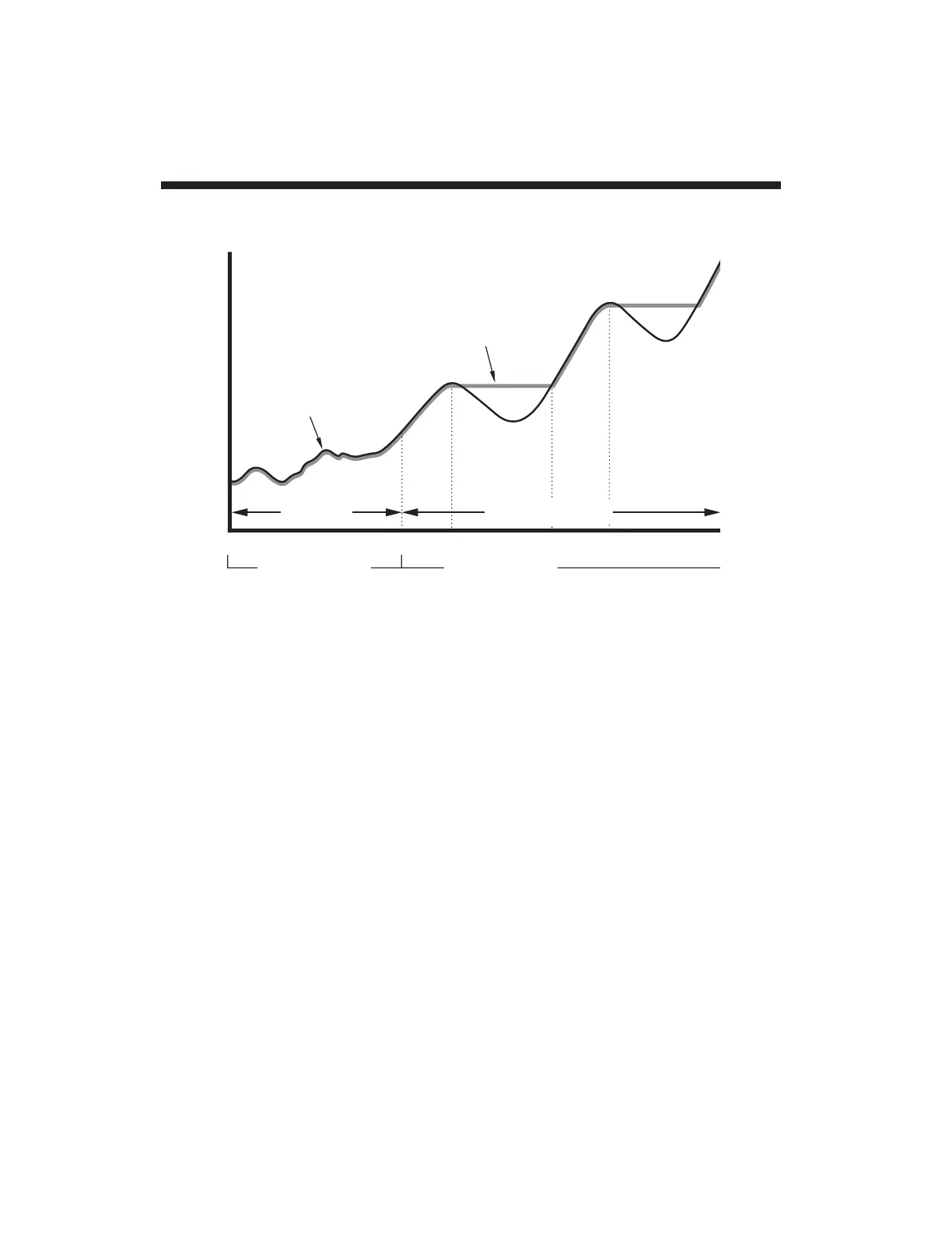
Fig. 16 shows the capture of successively lower-valued signal
maxima. Here, it is necessary to
reset
the "+PEAK" channel—to
get it "back on track," so to speak—somewhere along the rise of
the input toward the second, lower-valued peak (P
2
). This is done
by returning the "+PEAK" channel
momentarily
to "TRACK" mode
at time t
2
.
3. "–PEAK" Capture: PKN
Control of your 4077's "–PEAK" channel (No. 3) is strictly
analogous to that of the "+PEAK" channel, explained above. Thus,
Channel 3 can be made to "track" the ANALOG INPUT CHANNEL
1 either by entering a PEAK NEGATIVE (PKN) command of
PKN = TRK [CR]
Analog Peak Capture App. G
G.4
P
1
CHANNEL No. 1
(ANALOG INPUT)
P
2
t
0
t
1
t
2
t
3
t
4
PKP = TRK [CR]
or
LOGIC 1 at
"+PK IN" when
PKP = TRK [CR]
PKP = HLD [CR]
or
LOGIC 0 at
"+PK IN" when
PKP = TRK [CR]
TRACK + PEAK HOLD
CHANNEL No. 2
("+PEAK")
Fig. 15 Capture and
Hold of Successively
Higher-Valued Maxima

Questions and Answers:

Question and Answer IconNeed help?

Do you have a question about the DayTronic 4000 Series and is the answer not in the manual?

DayTronic 4000 Series Specifications

General IconGeneral
BrandDayTronic
Model4000 Series
CategoryMeasuring Instruments
LanguageEnglish

Related product manuals