or by applying a
Logic 1
level to the "–PK IN" input, WHILE THE
ABOVE PKN COMMAND IS IN EFFECT.
To place Channel 3 in "–PEAK HOLD" mode—i.e., to cause it to
continuously represent the
least positive
value experienced by the
Channel 1 since "–PEAK HOLD" mode was begun—you can either
command
PKN = HLD [CR]
or apply a
Logic 0
level to the "–PK IN" input WHILE THE PKN =
TRK [CR] COMMAND IS IN EFFECT.
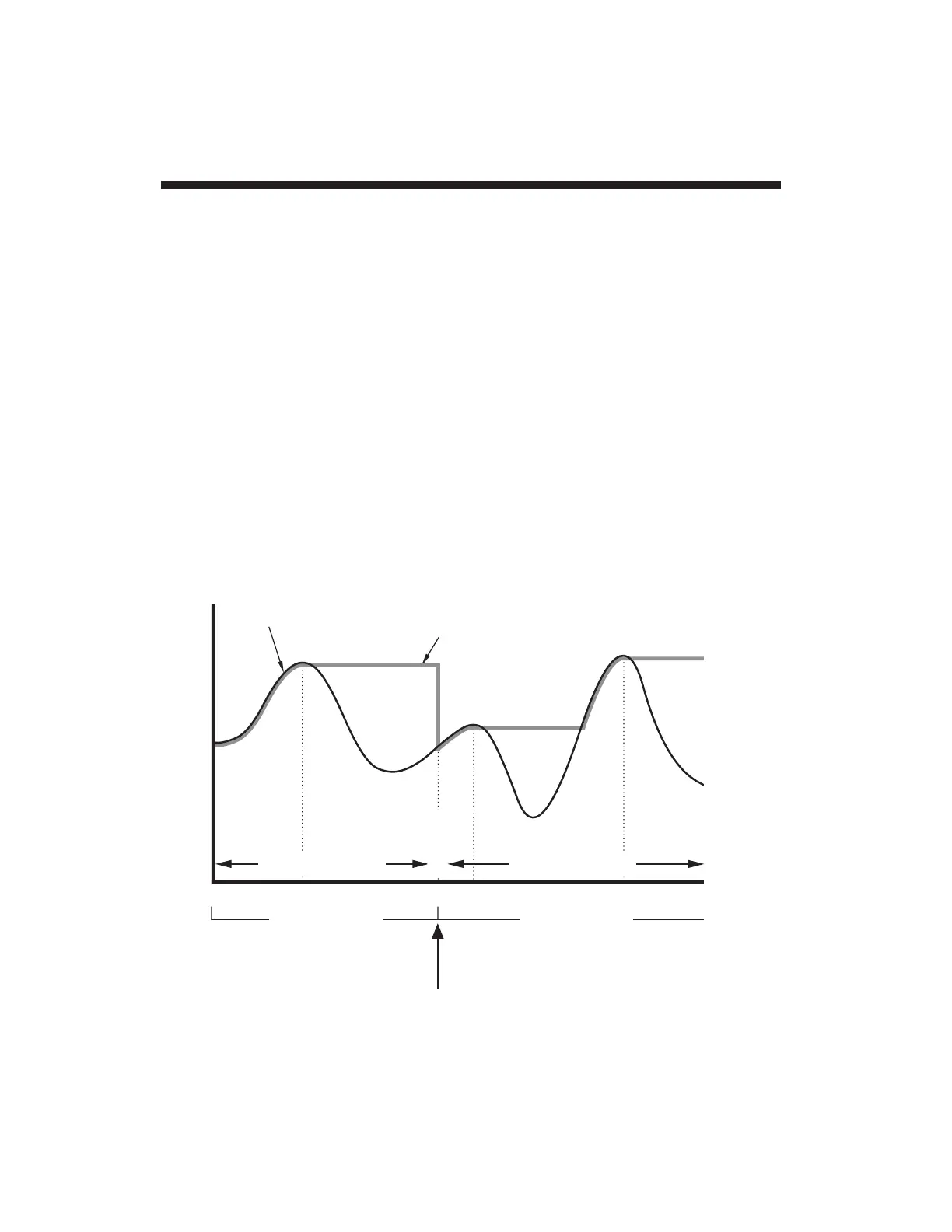
Fig. 17 shows the capture and hold of successively lower-valued
signal minima by the "–PEAK" channel (No. 3), after entering the
"–PEAK HOLD" mode at or prior to time t
0
. The
initial
signal
minimum (time t
0
) is held only until the input reaches a yet lower
value at time t
1
, at which time Channel 3 appears to begin to "track"
the input down to the first true negative peak (P
1
). This peak value
will be "captured" at time t
2
and held until a still lower input value is
App. G Analog Peak Capture

 Loading...