41
Make sure to turn it off before disassembly. Risk of electric shock.
PART NAME DESCRIPTION FIGURE
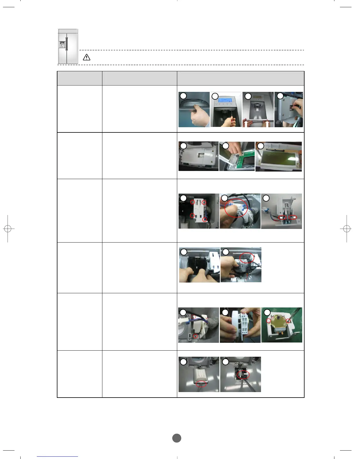
DISPENSER-
COVER
①
Disassemble circled Tray
Dispenser, disassemble the
Cover turning the two screw
counter-clockwise, Dispenser
pushing and lifting up.
② Disassemble the
connector like figure 2.
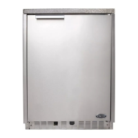
DISPENSER–
DISPLAY
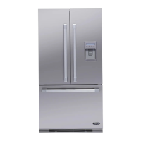
DISPENSER
–SUPPORT
MICRO
SWITCH
① Disassemble Dispenser
cover, disassemble the
circled 4 screws from the
assembly.
② Disassemble the
connector like figure 2.
③ Pull the circled ribs like
figure and then pull out
the Micro S/W
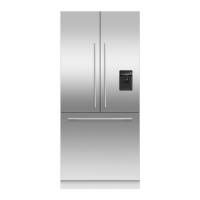
DISPENSER–
Ass’y COVER
ICE ROUTE
①
Disassemble
Dispenser cover(refer
to…), pull out the Guide
Ice Dispenser to the front.
② Push the Ass’y Cover
Ice Route to the left
using a tool like screw
driver and pull out.
DISPENSER–
CAM GEAR
MOTOR
①
Disassemble
Dispenser cover(refered
to...), disassemble the
circled 2 screws from
the assembly.
②
Disassemble the Cam from
the Motor like figure 2.
③ Disassemble the
circled 2 screws and
then pull Motor out.
DISPENSER–
PUSH LEVER
MICRO
SWITCH
①
Disassembling
Dispenser cover(refered
to…), push a tool like
‘
scpew
’ driver into the gap
and pull out.
② Push out the rib like
figure and then pull out
Micro Switch.
① Disassemble
dspenser cover, unscrew
4 screws and remove
Lamp cover.
② Disassemble the LCD
Assy connecter like figure.
③ Unscrew three scews
from the LCD.
1 2
1 1
1 3
2
1 3
2
1
2
1 3
2
1
2
BRANDSOURCE-SM(EN) 2007.1.23 10:31 AM 페이지41