52
Make sure to turn it off before disassembly. Risk of electric shock.
PART NAME DESCRIPTION FIGURE
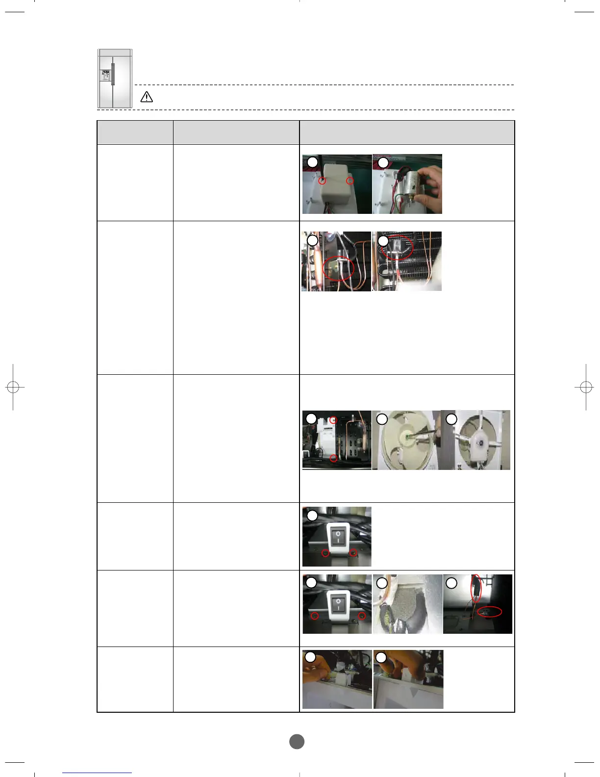
PCB-BOX :
CONDE NSER
① Disassemble circled 2
screws.
② Pull out Condenser from
PCB-BOX.
※ Be careful do not
change the terminals
during assembly.
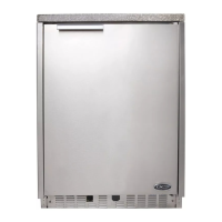
3-WAY VALVE
① Disassemble the Cover
Grill, disassemble the 3
welded sections.
② Disassemble 3-way
Valve then disassemble
2 screws and pull out
Housing.
※
Be careful do not change
the pipe during assembly
(red one is for Freezer)
Wrong connection of
pipes alter the gas flow
and cause performance
issues.
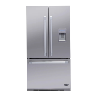
CONDE NSER
FAN MOTOR
① Pull out Fan Ass’y refer
to figure disassemble
circled 2 screws.
② First disassemble the
locking spring of Fan,
second disassemble 2
screws for mounting
Motor Cover, third
disassemble the wire
Housing and then pull
out the Motor by rotating
it.
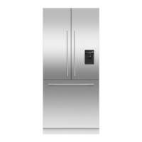
POWER
SWITCH
① Disassemble (circle)2
screws mounting bracket
and Housing connected
to PCB-BOX then pull
out Power switch from
the bracket.
INSULA TION
COVER OF
CONNE CTING
PIPE
① Disassemble 5 screws
located at the back of
Power switch.
② The pipes are covered
with insulation tubeing
left is for Freezer, right
is for Fridge.
DOOR
SWITCH
① After disassembling Cover
Grill, disassemble the
housing of switch like in the
Figure.
② Disassemble the switch by a
pulling down with squeezing
the lock hooks.
1
2
1
2
1
2 2
1
1
2 2
1
2
BRANDSOURCE-SM(EN) 2007.1.23 10:32 AM 페이지52