D E H L E R 3 4
1.5. Electrical systems
The boat possesses two electrical systems: 12 V direct current and 230 V alternating current.
Information on the scope and the equipment can be found in the operating instructions and the
contract specification. Take note of the operating instructions that include circuit diagrams for the
electrical systems and devices!
The electrical systems can be switched and controlled via the respective main control panels.
The main switch for the service battery is located behind the back rest of seat bench in the
saloon on the starboard side.
The main fuses and additional fuses are located in the navigation area and in the battery box in
the salon on the starboard side.
When operating the engine the main switches may not be
switched off, since this would destroy the diodes of the alternator.
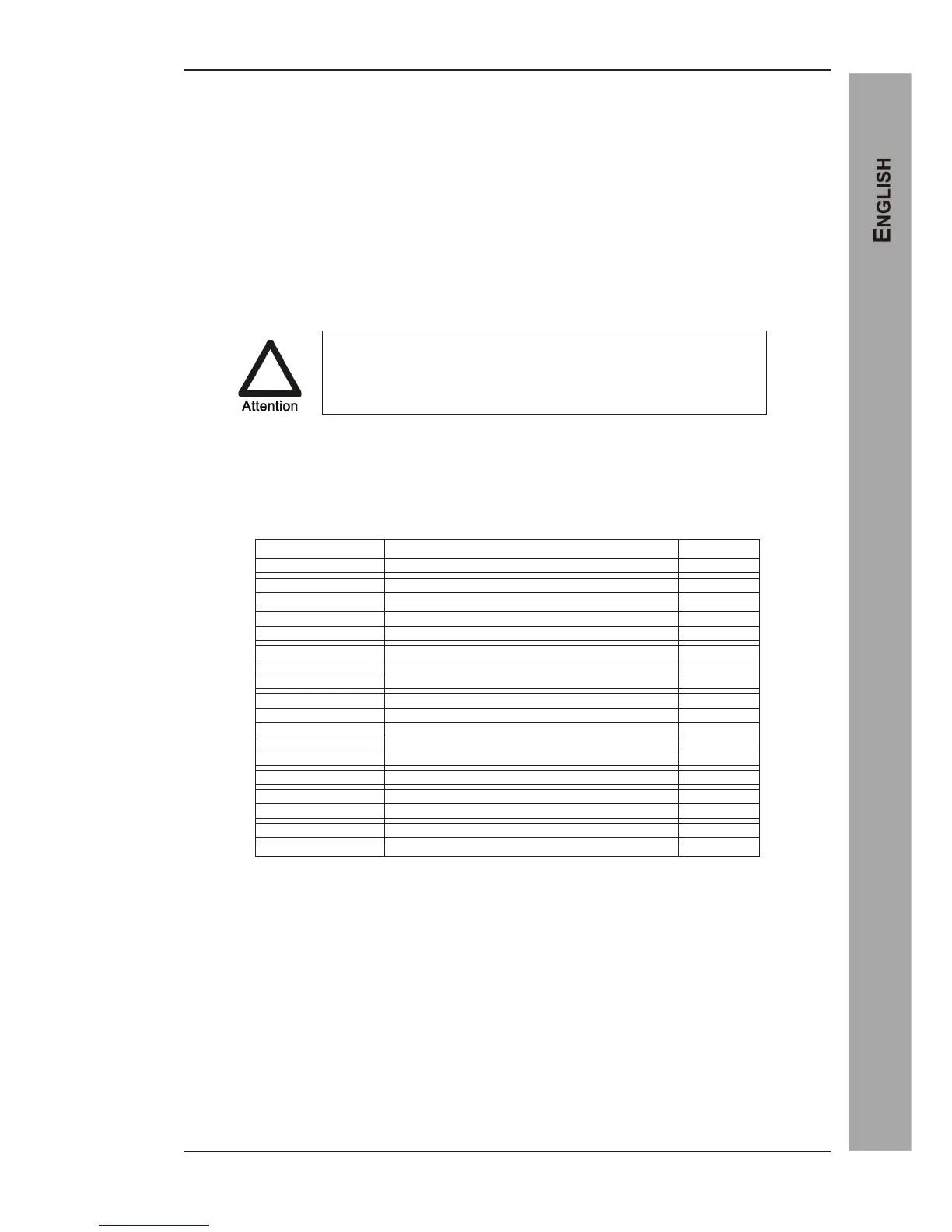
Fuse assignment Powerboard
Label power panel Appliance fuse