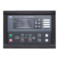
Additional operator´s panel AOP-2
CAN L CAN H
Terminal block
OFF
ON
App./Bootl.
End res.
CAN 1
Red
Red/white
DIN rail
5V DC
24V DC
+
-
+
-
Black
Black/white
Brown/white
Red
Brown/white
Red/white
Black/white
Black
Brown
6 - Black: GND
5 - Black/white: +5V DC
4 - Brown: Not used
3 - Red: CAN L
2 - Brown/white: CAN GND
1 - Red/white: CAN H
6 - Black: Relay common
5 - Black/white: Relay NO
4 - Brown: Relay NC
3 - Red: CAN L
2 - Brown/white: CAN GND
1 - Red/white: CAN H
Left CAN port (CAN 1) Right CAN port (CAN 2)
1
2
Cable shield
CAN 2
1...61...6
Comm. to
next units
NC
Common
NO
Status relay
59
57
R=120 Ω
For wiring details, please refer to "Wiring instructions" in this section.
If external I/O modules "Option H8" are used together with AOP-2, the total end resistance of
the AOP-2 and the external I/O controller must be 120 Ω.
A DC/DC converter for the DC supply voltage and 2 × 1 m cable with an RJ12 plug in one end
and stripped wires in the other end are included in the AOP-2 delivery.
AGC 100 installation instructions
4189340752 UK
Communication
DEIF A/S Page 28 of 28

 Loading...