27
26
25
12
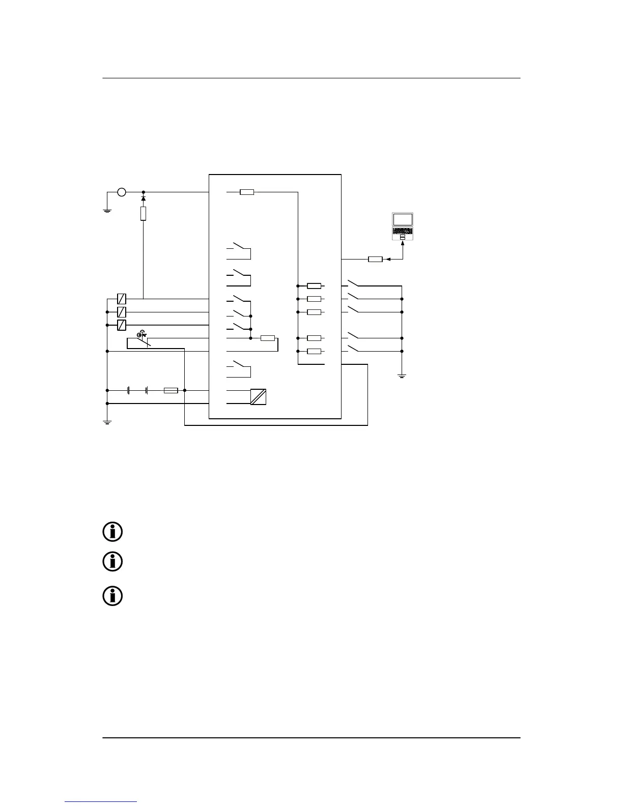
Controller
Oli pressure
1
2
R24
R23
RJ11
plug
R22
R21
24
23
22
21
20
19
4
3
15
14
13
11
10
9
Coolant temp.
Overspeed
Remote start
Start enable
Programming
tool
Battery
- +
Emer. STOP
Status
Start prep.
Starter
RUN coil
- +
F
Alarm horn
Alarm
Running
1N4007
Rex
D+D-
Charging
alternator
R26
Term. 12 can be used as alarm input if not
used for charger generator terminal D+
Rex: 12 V systems: 47 Ω 4 W
24 V systems: 100 Ω 6 W
If a stop coil is used, the REX resistor can be connected to the starter relay (crank).
The illustrated configuration is an example of settings. The use of the relays can be chosen
freely.
It is important to protect the unit against damage caused by high voltages. Therefore, the fuse
must not be more than 2 A slow-blow.
AGC 100 installation instructions
4189340752 UK
Wiring
DEIF A/S Page 11 of 28

 Loading...


