The RJ11 connector for the PC connection interface box is placed on the side of the unit.
3.1.1 Terminal description
For the relay outputs, the following terms will be used:
NO means Normally Open.
NC means Normally Closed.
Com. means common terminal for the individual relay.
AGC 100 installation instructions
4189340752 UK
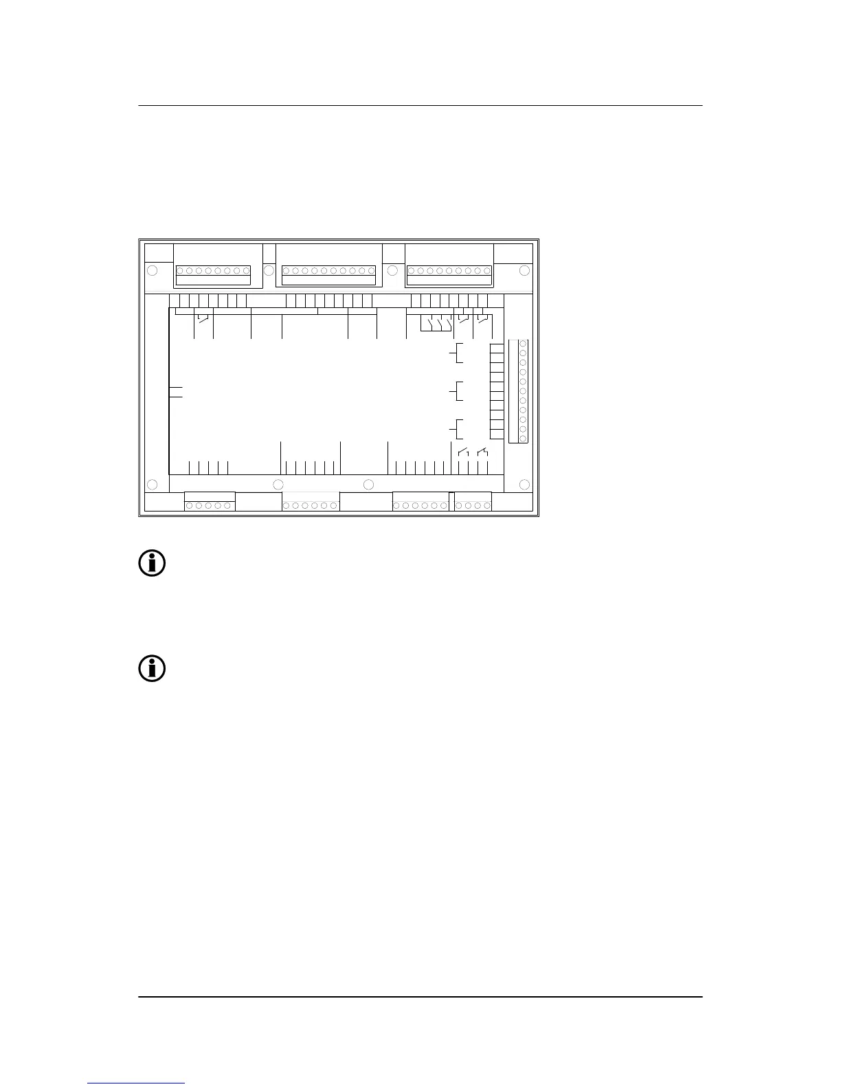
Terminals
DEIF A/S Page 7 of 28

 Loading...


