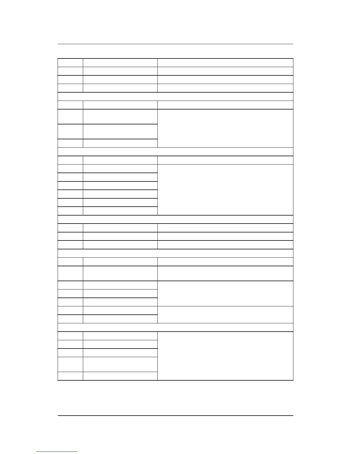
Terminal Technical data Description
1 Power supply + 6 to 36 V DC (UL/cUL Listed: 7.5 to 32.7 V DC)
2 Power supply – GND
3-4 Status out/configurable See note*. Contact ratings 1 A 24 V DC/V AC Resistive
Multi-functional inputs
5 Common Common for terminal 6, 7 and 8
6 RMI/4 to 20 mA/digital input/
Pt1000
Configurable
7 RMI/4 to 20 mA/digital input/
Pt1000
8 RMI/4 to 20 mA/digital input
Digital inputs
9 Common Common for terminal 10 to 15
10 Digital input Configurable
11 Digital input
12 Digital input
13 Digital input
14 Digital input
15 Digital input
Tacho RPM input
16 RPM input (MPU) Magnetic pickup tacho generator (2-wire)
17 RPM-GND Common for RPM input
18 RPM input (W/L) Magnetic pickup. PNP, NPN or charge alternator W terminal
Relay outputs
19 Common Common for emergency stop terminal 20
20 Emergency stop and common
for 21 to 23
Common for relay 21, 22 and 23 and input for emergency
stop**
21 Relay output Configurable. Function NO. Contact ratings 2 A 30 V DC/V
AC
22 Relay output
23 Relay output
24-25 Relay output Configurable. Function NO. Contact ratings 8 A 30 V DC/V
AC
26-27 Relay output
3-phase mains voltage input
28 Mains voltage L1 Mains voltage and frequency
29 Mains neutral
30 Mains voltage L2
31 Not used, must not be connec-
ted
32 Mains voltage L3
AGC 100 installation instructions
4189340752 UK
Terminals
DEIF A/S Page 8 of 28

 Loading...


