MIB Installation Instructions and Reference Handbook
DEIF A/S
Page 12 of 50
Electrical connection
Terminals
The MIB has the following rows of terminals on the rear side:
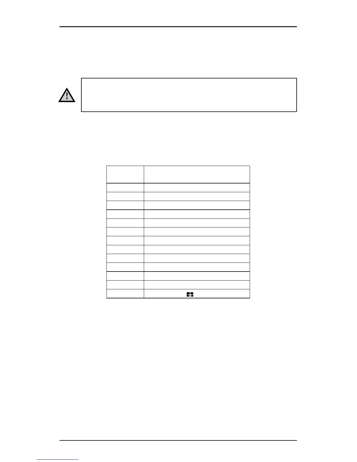
Current, voltage input and aux. power terminals
Terminal
number
Description
1 I11 Current phase 1 in
2 I12 Current phase 1 out
3 I21 Current phase 2 in
4 I22 Current phase 2 out
5 I31 Current phase 3 in
6 I32 Current phase 3 out
7 V1 Voltage phase 1
8 V2 Voltage phase 2
9 V3 Voltage phase 3
10 Vn Voltage neutral
11 Auxiliary power supply L (+)
12 Auxiliary power supply N (-)
13 Safety earth
Only qualified personnel should do the wire connection work.
Make sure the power supply is cut off. Failure to do this may
result in severe injury or death.