PPM Installation Instructions
DEIF A/S Page 39 of 69
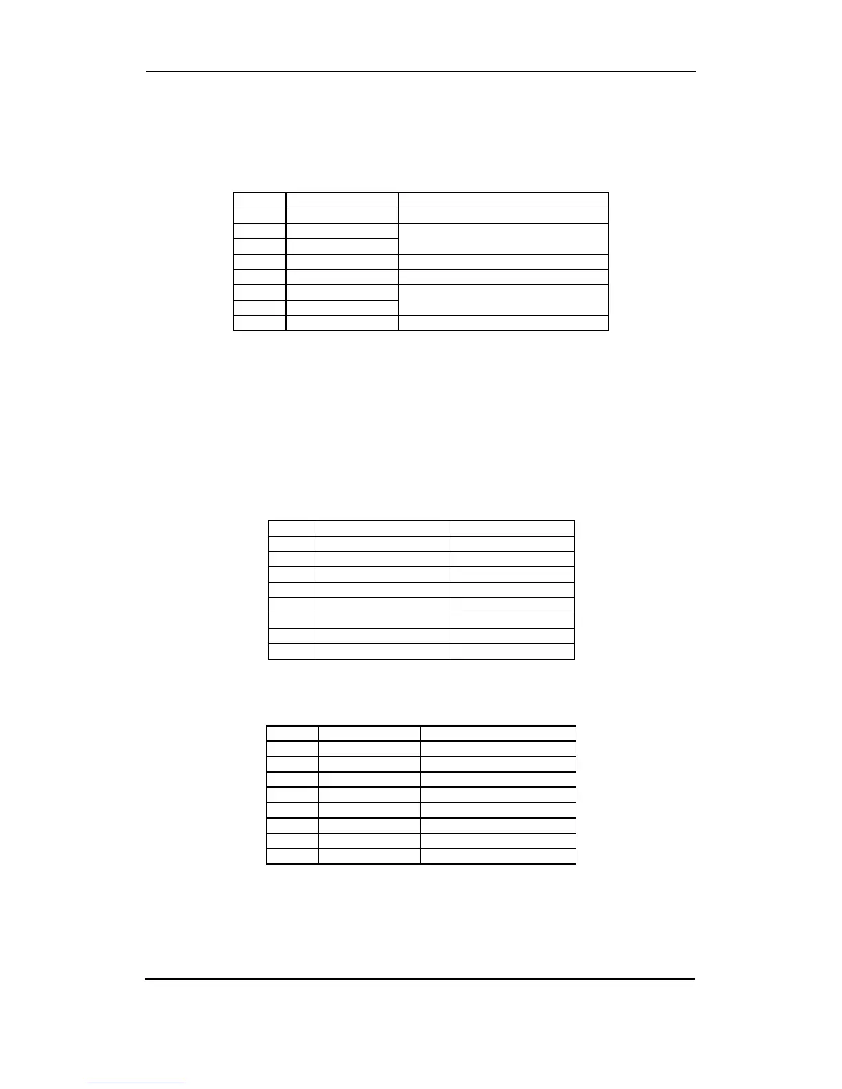
Slot #6, optional I/Os
Option F1
Analogue transducer output.
Term. Function Description
90 Not used
91 0 Analogue output 1, selectable
92 0(4) - 20 mA out
93 Not used
94 Not used
95 0 Analogue output 2, selectable
96 0(4) - 20 mA out
97 Not used
These outputs are active outputs, meaning that they have an internal power supply. The outputs
are galvanically separated from each other and from the rest of the unit. Via the display or the
PC programming software individual outputs can be selected to represent any AC measuring
value and related values, e.g. power, power factor, frequency etc. Outputs can be selected to be
either 0…20 mA or 4…20 mA in the PC utility software. If necessary the current outputs can be
converted to voltage using a resistor across the terminals (500 will convert the 0-20 mA into 0-
10V DC).
Option M15
4 x analogue 4-20 mA inputs.
Term. Function Description
90 Input 90 common Common
91 Analogue input 91+ 4-20 mA in
92 Input 92 common Common
93 Analogue input 93+ 4-20 mA in
94 Input 94 common Common
95 Analogue input 95+ 4-20 mA in
96 Input 96 common Common
97 Analogue input 97+ 4-20 mA in
Option M16
7 x binary inputs.
Term. Function Description
90 Common Common
91 Digital input Configurable
92 Digital input Configurable
93 Digital input Configurable
94 Digital input Configurable
95 Digital input Configurable
96 Digital input Configurable
97 Digital input Configurable