Preliminary
941322_VMS Instruction Book 2006.pdf2009-09-07
No. Name Range Default Description/optionsNo. Name Range Default Description/options
0 = no acidic cleaning0 = no acidic cleaning
1 = one alkaline, one acidic cleaning1 = one alkaline, one acidic cleaning
2 = two alkaline, one acidic cleaning2 = two alkaline, one acidic cleaning
3 = etc.3 = etc.
Maintenance an calibration
The following points are important to sustain
correct dosing of etergents. Note that
these two tasks should be performed by an
authorised DeLaval service engineer.
• The tubes in the peristaltic pumps should
be replaced at least two times a year.
• The dosing volume (P6-P8) of the
detergent pumps should be checked
every third month. The dosing capacity
(P32-P34) may need to be adjusted.
Starting cleaning or rinsing
from the touch screen
Note: Any ongoing backflush process must
first be finished before cleaning or rinsing
can be started.
1. Ensure that the milking station is in
manual mode.
2. Remove any cow that might be in the
milking station.
After treatment window
Note: Both gates should be closed to
prevent a cow from entering before the
system cleaning has been started. Closing
and opening gates is done in the Stall
control window.
3. Press the tab After Treatment on the
touch screen to display the After treatment
window.
4. In the After treatment window, press the
Cleaning and Rinsing button. This will open
the Cleaning and rinsing window.
2 Overview
Control Valve
Control Valve
Control Valve
Control Valve
Control Valve
Air washAir washAir wash
Wireless bridge
LPNMLKJ
DDD
Q
B
A
E
F
G
H
C
275794
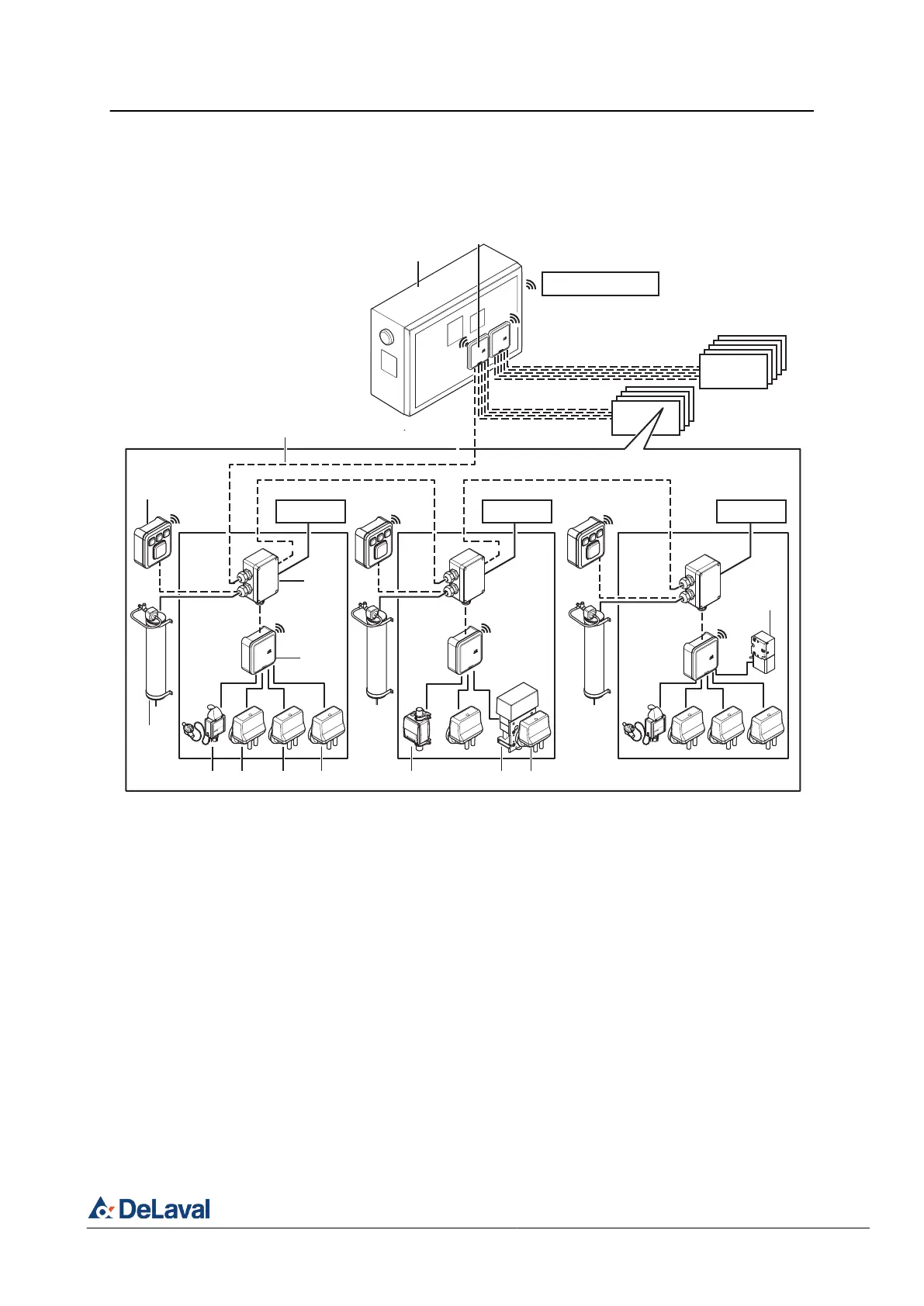
Fig. 4: Milking automation architecture.
A: Infrastructure box
B: Communication and control module
C: Local interconnection network bus
D: Automation panels
E: Input/output module
F: Button module
G: Junction box
H: Comfort start functionality
J: Milk meter
K: Control valve
L: Pulsator
M: Control valve
N: Flow indicator
P: Regulator block
Q: MAC-valve for air retraction
The milking automation system consists of mod-
ules with different functionalities interconnected
in a milking automation network to each other
through a local interconnetion network (LIN) bus.
Up to three milking point input/output modules
(IOM) are connected on the same local intercon-
netion network bus. The input/output module
controls the milking process in one milking point.
The button module (BM) is connected to the
DeLaval milking automation MA200 (Test installation)
General description
© DeLaval 2019.
2019-05-31, Version 1 28 (62)