Preliminary
941322_VMS Instruction Book 2006.pdf2009-09-07
No. Name Range Default Description/optionsNo. Name Range Default Description/options
0 = no acidic cleaning0 = no acidic cleaning
1 = one alkaline, one acidic cleaning1 = one alkaline, one acidic cleaning
2 = two alkaline, one acidic cleaning2 = two alkaline, one acidic cleaning
3 = etc.3 = etc.
Maintenance an calibration
The following points are important to sustain
correct dosing of etergents. Note that
these two tasks should be performed by an
authorised DeLaval service engineer.
• The tubes in the peristaltic pumps should
be replaced at least two times a year.
• The dosing volume (P6-P8) of the
detergent pumps should be checked
every third month. The dosing capacity
(P32-P34) may need to be adjusted.
Starting cleaning or rinsing
from the touch screen
Note: Any ongoing backflush process must
first be finished before cleaning or rinsing
can be started.
1. Ensure that the milking station is in
manual mode.
2. Remove any cow that might be in the
milking station.
After treatment window
Note: Both gates should be closed to
prevent a cow from entering before the
system cleaning has been started. Closing
and opening gates is done in the Stall
control window.
3. Press the tab After Treatment on the
touch screen to display the After treatment
window.
4. In the After treatment window, press the
Cleaning and Rinsing button. This will open
the Cleaning and rinsing window.
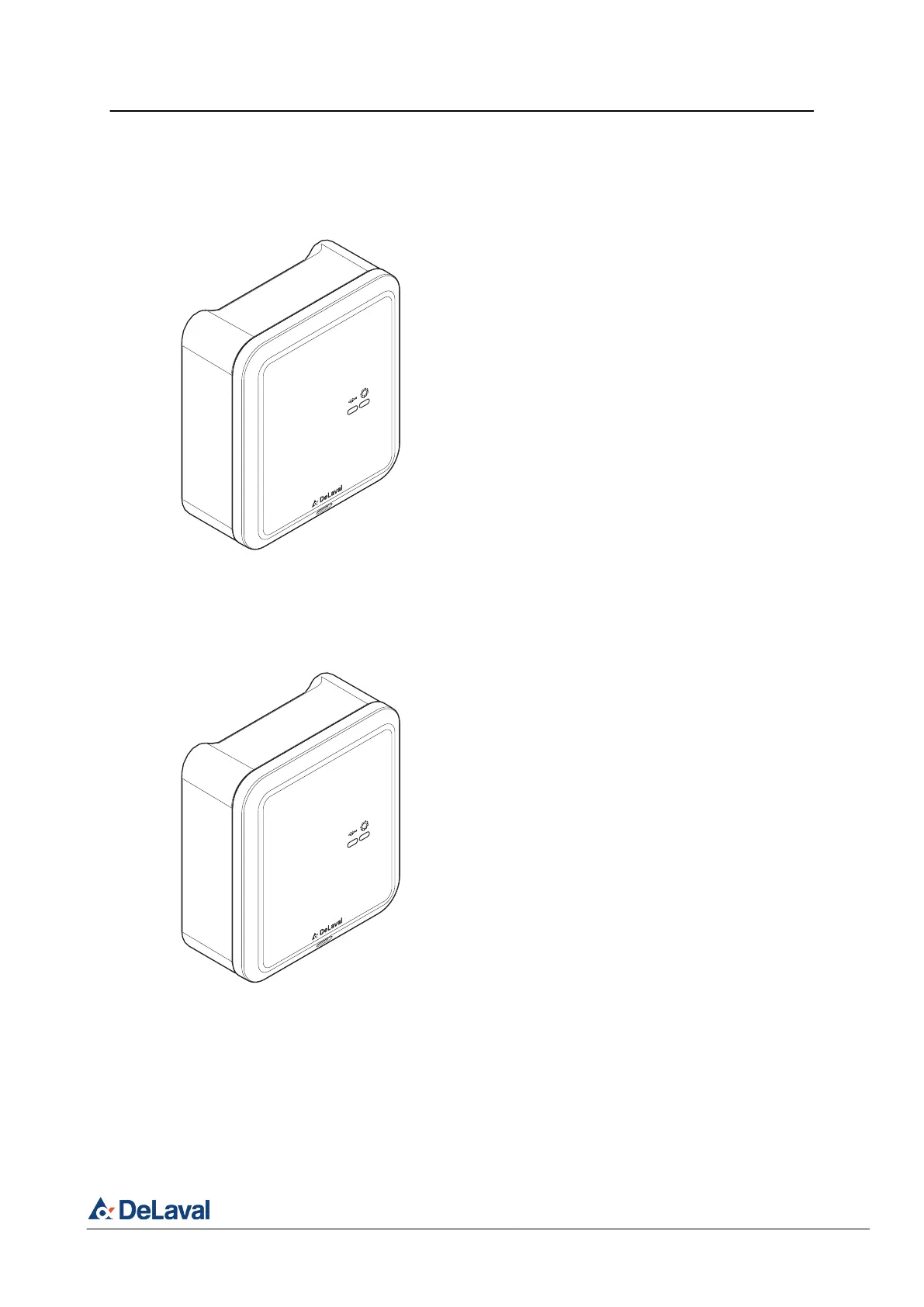
2.1.2 Input/output module
The input/output module recieves user com-
mands from the button module through the local
interconnection network bus or the comfort start
functionality. From these commands the input/
output module controls the milking and cleaning
processes. At the milking point and in the milking
or cleaning process the input/output module
interacts with a flow sensor and it controls the
control valves and the regulator block. It interfa-
ces with the system controller through a commu-
nication and control module. The input/output
module is connected to a communication and
control module through the local interconnection
network. Two light indicators on the input/output
module indicates the current status.
One input/output module is needed for each milk-
ing point.
2.1.3 Communication and control module
The communication and control module routes
data between the devices in the the local inter-
connection network (milking points) and the
ethernet devices (system controller and rotary
controller). The last communication and control
module in the system stores the system installa-
tion configuration for the system interaction. Two
light indicators on the communication and control
module indicates the current status.
269067
Fig. 6: Input/output module IOM.
269067
Fig. 7: Communication and control module CCM.
DeLaval milking automation MA200 (Test installation)
General description
© DeLaval 2019.
2019-05-31, Version 1 30 (62)