22 Part Number: 9291458 REV00 12/19
Installation Section 2
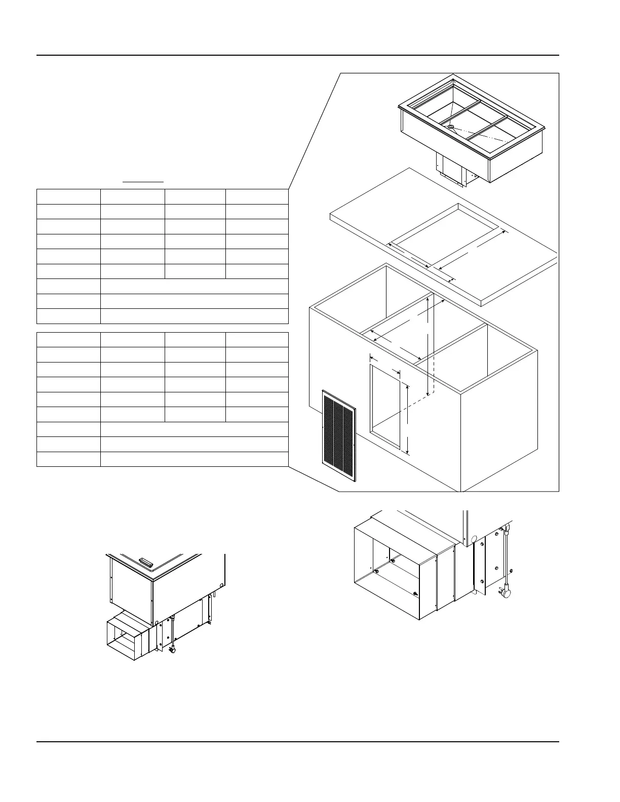
SELFCONTAINED REFRIGERATED DROPIN UNITS
8100-FAP
For any non-standard installation consult the factory.
1. Install a GFCI receptacle a minimum of 14” (36cm) up
from the cabinet bottom inside the partitions. We
recommend installing a remote located power switch
for ease of use.
2. Cabinet interior minimum dimensions:
Dimension N8131-FAP N8144-FAP
A 30.25"/77cm 43"/109cm
B 27.75"/70cm 27.75"/70cm
C 26"/66cm 26"/66cm
D 30.25"/77cm 43"/109cm
E 25.5"/65cm 25.5”/65cm
F Min. 2.75”/7cm - Max. 4.75”/12cm
G 12”
H 23.50”
Dimension N8157-FAP N8169-FAP N8182-FAP
A 55.75"/142cm 68.5"/174cm 81.25"/206cm
B 27.75"/70cm 27.75"/70cm 27.75"/70cm
C 26"/66cm 26"/66cm 26"/66cm
D 55.75"/142cm 68.5"/174cm 81.25"/206cm
E 25.5"/65cm 25.5"/65cm 25.5"/65cm
F Min. 2.75”/7cm - Max. 4.75”/12cm
G 15.75”
H 23.50”
3. Place the condensing unit through the counter cutout.
4. Extend the telescoping duct from the front of the
condensing unit to the back of the louver. This will
prevent recirculation of discharge air. Export models do
not have a telescoping duct, skip to step 6.
5. Put eight provided screws through the telescoping
duct side walls to hold it at the desired depth.
C
E
D
A
B
G
F
H
Use Screws to Secure Desired Depth
3 of 8 Screws Shown
6. Partitions must fully extend front to back and top to
bottom.
7. Louver cutout must extend to bottom of cabinet and
align with condenser face.
NOTE: The louver provided must be installed in front of