Table 5. Ops panel functions
No. Indicator Status
1 Unit identification display (UID) Green (seven-segment display: enclosure sequence)
2 System power on/Standby
Constant green: positive indication
Constant amber: system in standby (not operational)
3 Module fault Constant or blinking amber: fault present
4 Logical status Constant or blinking amber: fault present
5 Top drawer fault Constant or blinking amber: fault present in drive, cable, or sideplane
6 Bottom drawer fault Constant or blinking amber: fault present in drive, cable, or sideplane
Unit identification display
The UID is a dual seven-segment display that shows the numerical position of the enclosure in the cabling sequence. This is also called the
enclosure ID. The controller enclosure ID is 0.
System power on/Standby LED (green/amber)
LED is amber when only the standby power is available (non-operational). LED is green when system power is available (operational).
Module fault LED (amber)
LED turns amber when experiencing a system hardware fault. This LED helps you identify the component causing the fault, which can be
associated with a Fault LED on a controller module, IOM, PSU, FCM, DDIC, or drawer.
Logical status LED (amber)
This LED indicates a change of status or fault from something other than the enclosure management system. This may be initiated from
the controller module or an external HBA. The indication is typically associated with a DDIC and LEDs at each disk position within the
drawer, which help to identify the DDIC affected.
Drawer fault LEDs (amber)
This LED indicates a disk, cable, or sideplane fault in the drawer indicate: Top (Drawer 0) or Bottom (Drawer 1).
CAUTION:
The sideplanes on the enclosure drawers are not hot swappable or customer serviceable.
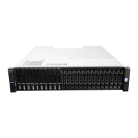
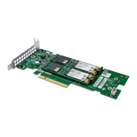
Controller modules
This section describes the controller modules used in 12 Gb/s storage enclosures. They are mechanically and electrically compliant to the
latest SBB v2.1 specification.
The following figure shows a 4-port FC/iSCSI controller module aligned for use in the top slot located on the 2U enclosure rear panel. The
controller module is also properly aligned for use in either slot located on the 5U84 enclosure rear panel.
Figure 30. Controller module – rear orientation
Storage system hardware
21

 Loading...