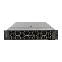
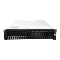
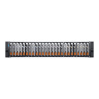
2U enclosure LEDs
PCM LEDs
Under normal conditions, the PCM OK LEDs will be a constant green.
Table 11. PCM LED states
PCM OK
(Green)
Fan Fail
(Amber)
AC Fail
(Amber)
DC Fail
(Amber)
Status
Off Off Off Off No AC power on any PCM
Off Off On On No AC power on this PCM only
On Off Off Off AC present; PCM working correctly
On Off Off On PCM fan speed is outside acceptable limits
Off On Off Off PCM fan has failed
Off On On On PCM fault (above temperature, above voltage, above current)
Off Blinking Blinking Blinking PCM firmware download is in progress
Ops panel LEDs
The Ops panel displays the aggregated status of all the modules. See 2U enclosure Ops panel. The Ops panel LEDs are defined in the
following table.
Table 12. Ops panel LEDs
System Power
(Green/Amber)
Module Fault
(Amber)
Identity
(Blue)
LED
display
Associated LEDs /
Alarms
Status
On Off Off X 5V standby power present, overall power
failed or switched off
On On On On Ops panel power on (5s) test state
On Off Off X Power on, all functions good
On On X X PCM fault LEDs, fan
fault LEDs
Any PCM fault, fan fault, above or below
temperature
On On X X SBB module LEDs Any SBB module fault
On On X X No module LEDs Enclosure logical fault
On Blink X X Module status LED
on SBB module
Unknown (invalid or mixed) SBB module
type installed, I
2
C bus failure (inter-SBB
communications). EBOD VPD configuration
error
On Blink X X PCM fault LEDs, fan
fault LEDs
Unknown (invalid or mixed) PCM type
installed or I
2
C bus failure (PCM
communications)
X Blink Enclosure identification or invalid ID selected
X= Disregard
Actions:
• If the Ops panel Module Fault LED is on, check the module LEDs on the enclosure rear panel to narrow the fault to a CRU, a
connection, or both.
• Check the event log for specific information regarding the fault, and follow any Recommended Actions.
• If installing an IOM CRU:
• Remove and reinstall the IOM per the instructions in Removing a controller module.
• Check the event log for errors.
Troubleshooting and problem solving
31
 Loading...


