blank must be installed in slot B to ensure sufficient airflow through the enclosure during operation. For 5U84 enclosures, an controller
module must be installed in both slot A and slot B.
Upgrading to dual-controller configuration
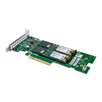
You can upgrade a 2U single-controller module configuration by adding a second controller module in slot B.
Controller module B can be added while controller module A continues to process host I/O requirements. However, we recommend
scheduling configuration changes during a maintenance window with low or no I/O activity.
Data is not impacted when a controller module B is inserted into the enclosure, but we recommended doing a complete data backup
before proceeding.
NOTE:
• When a controller module B is inserted, the redundancy setting is automatically changed from Single Controller
to Active-Active ULP (Unified LUN Presentation). No manual changes are necessary.
• If PFU (partner firmware upgrade) is enabled, when you add controller module B, the system automatically updates
the firmware on second controller module to match the firmware version on the first controller module.
1.
Type the following CLI command to confirm that redundancy is configured as Single Controller Mode:
show advanced-settings
This step confirms that controller module A does not report controller module B as missing.
2. Remove the controller blank from slot B.
3. Grasp the controller module with both hands, and with the latch in the open position, orient the module and align it for insertion into
slot B.
4. Ensuring that the controller module is level, slide it into the enclosure as far as it will go.
A controller module that is only partially seated will prevent optimal performance of the controller enclosure. Verify that the controller
module is fully seated before continuing.
5. Set the module in position by manually closing the latch.
You should hear a click as the latch handle engages and secures the controller module to its connector on the back of the midplane.
6. Connect the cables.
7. Map the host ports on controller module B.
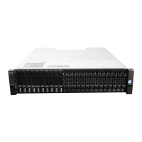
Enclosure management
The enclosure is mechanically and electrically compliant with the Storage Bridge Bay (SBB) v 2.1 specification.
SBB modules actively manage the enclosure. Each module has a SAS expander with its own storage enclosure processor (SEP) that
provides a SES target for a host to interface to, through the ANSI SES (SCSI Enclosure Services) standard. If one of these modules fails,
the other module continues to operate.
Management interfaces
When the hardware installation is complete, access the controller module web-based management interface—ME Storage Manager—to
configure, monitor, and manage the storage system. The controller module also provides a command-line interface (CLI) to support
command line entry and scripting. For details, see the Dell EMC PowerVault ME4 Series Storage System CLI Guide for your system.
Operation
CAUTION:
Operation of the enclosure with any CRU modules missing will disrupt the airflow, and the enclosure will not
receive sufficient cooling. It is essential that all slots hold modules before the enclosure system is used. Empty drive
slots (bays) in 2U enclosures must hold blank drive carrier modules.
• Read the module bay caution label affixed to the module being replaced.
• Replace a defective power cooling module (PCM) with a fully operational PCM within 24 hours. Do not remove a defective PCM
unless you have a replacement model of the correct type ready for insertion.
• Before removal/replacement of a PCM or power supply unit (PSU), disconnect power supply from the module to be replaced.
6
Storage system hardware

 Loading...