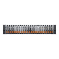
Supercapacitor pack
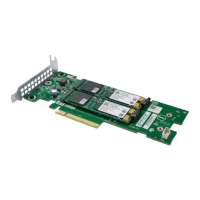
To protect controller module cache in case of power failure, each controller enclosure model is equipped with supercapacitor technology,
in conjunction with CompactFlash memory, built into each controller module to provide extended cache memory backup time. The
supercapacitor pack provides energy for backing up unwritten data in the write cache to the CompactFlash, in the event of a power
failure. Unwritten data in CompactFlash memory is automatically committed to disk media when power is restored. In the event of power
failure, while cache is maintained by the supercapacitor pack, the Cache Status LED blinks at a rate of 1/10 second on and 9/10 second
off.
Controller failure when a single-controller is
operational
The following information applies to 2U single controller enclosures when the controller fails. The following information also applies or 2U
and 5U dual-controller enclosures when one of the controllers is down and the other controller fails.
Cache memory is flushed to CompactFlash in the case of a controller failure or power loss. During the write to CompactFlash process, only
the components needed to write the cache to the CompactFlash are powered by the supercapacitor. This process typically takes 60
seconds per 1Gbyte of cache. After the cache is copied to CompactFlash, the remaining power left in the supercapacitor is used to refresh
the cache memory. While the cache is being maintained by the supercapacitor, the Cache Status LED blinks at a rate of 1/10 second on
and 9/10 second off.
NOTE: Remove the CompactFlash memory card only if recommended by Dell EMC technical support.
Transportable cache only applies to single-controller configurations. In dual-controller configurations featuring one
healthy partner controller, there is no need to transport failed controller cache to a replacement controller because the
cache is duplicated between the controllers, provided that the volume cache is set to standard on all volumes in the pool
owned by the failed controller.
Cache status LED – corrective action
If the controller has failed or does not start, check if the Cache status LED is on or blinking.
Table 10. LEDs: Rear panel Cache Status
Status Action
Cache status LED status is off, and the controller does
not boot.
If the problem persists, replace the controller module.
Cache status LED is off, and the controller boots. The system has flushed data to disks. If the problem persists, replace the
controller module.
Cache status LED blinks at a 1:10 rate - 1 Hz, and the
controller does not boot.
You may need to replace the controller module.
Cache status LED blinks at a 1:10 rate - 1 Hz, and the
controller boots.
The system is flushing data to CompactFlash. If the problem persists, replace
the controller module.
Cache status LED blinks at a 1:1 rate - 2 Hz, and the
controller does not boot.
You may need to replace the controller module.
Cache status LED blinks at a 1:1 rate - 1 Hz, and the
controller boots.
The system is in self-refresh mode. If the problem persists, replace the
controller module.
Transporting cache
To preserve the existing data stored in the CompactFlash, you must transport the CompactFlash from the failed controller to a
replacement controller. Failure to transport the CompactFlash will result in loss of data stored in the cache module. For the location of the
CompactFlash, see
Transporting CompactFlash.
CAUTION:
Remove the controller module only after the copy process has completed, which is indicated by the Cache
Status LED being off, or blinking on 1:10 rate.
Storage system hardware 27
 Loading...


