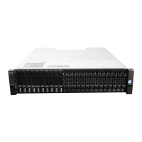
• For information about enclosure front panel LEDs, see 2U enclosure Ops panel.
• For information about disk LEDs for LFF and SFF disk modules, see Verify front panel LEDs.
• For information about the optional 2U enclosure front bezel, see Figure 7. Attaching or removing the 2U enclosure
front bezel.
2U enclosure rear panel
Alphabetic designators on controller modules or IOMs and numeric designators on PCMs indicate slot sequencing for the modules used in
2U enclosures. Controller modules, IOMs, and PCMs are available as CRUs. The ME4 Series RBODs use 4-port controller modules. These
RBODs support the ME412/ME424/ME484 EBODs for optionally adding storage.
Figure 10. 2U controller enclosure—rear panel components (4-port FC/iSCSI)
1. Power cooling module slot 0 2. Power cooling module slot 1
3. Controller module slot A 4. Controller module slot B
Figure 11. 2U controller enclosure—rear panel components (4-port iSCSI 10Gbase-T)
1.
Power cooling module slot 0 2. Power cooling module slot 1
3. Controller module slot A 4. Controller module slot B
Figure 12. 2U controller enclosure—rear panel components (4-port SAS)
1.
Power cooling module slot 0 2. Power cooling module slot 1
3. Controller module slot A 4. Controller module slot B
NOTE: The preceding figures show dual controller module configurations. Alternatively, you can configure the 2U
controller enclosure with a single controller module. In single controller module configurations, the controller module is
installed in slot A, and a blank plate is installed in slot B.
Figure 13. 2U expansion enclosure—rear panel components
1.
Power cooling module slot 0 2. Power cooling module slot 1
Storage system hardware 11

 Loading...