3. IOM slot A 4. IOM slot B
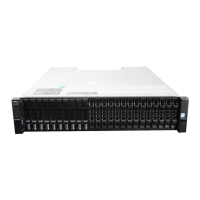
2U rear panel components
This section describes the controller module, expansion enclosure IOM, and power cooling module components.
Controller module
The top slot for holding controller modules is designated slot A and the bottom slot is designated slot B. The face plate details of the
controller modules show the modules aligned for use in slot A. In this orientation, the controller module latch shown at the bottom of the
module and it is in a closed/locked position. The following figures identify the ports on the controller modules. See
12 Gb/s controller
module LEDs for LED identification.
The Converged Network Controller (CNC) ports on the 4-port FC/iSCSI controller module can be configured with 16Gb/s FC SFPs or 10
GbE iSCSI SFPs.
Figure 14. 4-port FC/iSCSI controller module detail
1.
Back-end expansion SAS port 2. Ethernet port used by management interfaces
3. USB serial port (CLI) 4. 3.5 mm serial port (CLI)
5. 3.5 mm serial ports (service only) 6. Reset
7. CNC ports (ports 3, 2, 1, 0)
The following figure shows iSCSI 10Gbase-T host interface ports that ship configured with pre-installed external connectors.
Figure 15. 4-port iSCSI 10Gbase-T controller module detail
1.
Back-end expansion SAS port 2. Ethernet port used by management interfaces
3. USB serial port (CLI) 4. 3.5 mm serial port (CLI)
5. 3.5 mm serial ports (service only) 6. 10Gbase-T ports (ports 3, 2, 1, 0)
The following figure shows SAS host interface ports that ship configured with 12 Gb/s mini-SAS HD (SFF-8644) external connectors.
12
Storage system hardware

 Loading...