Figure 16. 4-port mini-SAS HD controller module detail
1. Back-end expansion SAS port 2. Ethernet port used by management interfaces
3. USB serial port (CLI) 4. 3.5 mm serial port (CLI)
5. 3.5 mm serial ports (service only) 6. Reset button
7. SAS ports (ports 3, 2, 1, 0)
Expansion enclosure IOM
The following figure shows the IOM used in supported expansion enclosures for adding storage. Ports A/B/C ship configured with 12
Gb/s mini-SAS HD (SFF-8644) external connectors.
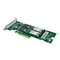
Figure 17. IOM detail – ME412/ME424/ME484
1.
3.5 mm serial port (service only) 2. SAS expansion ports
3. SAS expansion port B (disabled) 4. Ethernet port (disabled)
NOTE: For RBOD/EBOD configurations:
• When the IOM shown in Figure 17. IOM detail – ME412/ME424/ME484 is used with ME4 Series controller modules
for adding storage, the middle HD mini-SAS expansion labeled port B is disabled by the firmware.
• The Ethernet port on the IOM is not used in controller/expansion enclosure configurations, and is disabled.
Power cooling module
The following figure shows the power cooling module (PCM) used in controller enclosures and optional expansion enclosures. The PCM
includes integrated cooling fans. The example shows a PCM oriented for use in the left PCM slot of the enclosure rear panel.
Figure 18. Power cooling module (PCM)
1.
PCM OK LED (Green) 2. AC Fail LED (Amber/blinking amber)
Storage system hardware 13

 Loading...