6. ClickYes to continue; otherwise, click No. If you clicked Yes, a message describes shutdown activity.
NOTE:
• If an iSCSI port is connected to a Microsoft Windows host, the following event is recorded in the Windows event log:
Initiator failed to connect to the target.
• See the
Dell EMC PowerVault ME4 Series Storage System Administrator’s Guide
for additional information.
Using the CLI
1. Log-in to the CLI.
2. In your dual-controller system, verify that the partner controller is online by running the command: show controllers
3. Shut down the failed controller—A or B—by running the command: shutdown a or shutdown b
The blue OK to Remove LED (back of enclosure) illuminates to indicate that the controller module can be safely removed.
4. Illuminate the white Identify LED of the enclosure that contains the controller module to remove by running the command: set led
enclosure 0 on
The Display LED on the Ops panel located on the enclosure left ear will be blinking green when theset led enclosure 0 on
command is invoked.
NOTE:
See the
Dell EMC PowerVault ME4 Series Storage System CLI Guide
for additional information.
Verifying component failure
Select from the following methods to verify component failure:
• Use the ME Storage Managerto check the health icons/values of the system and its components to either ensure that everything is
okay, or to drill down to a problem component. The ME Storage Manager uses health icons to show OK, Degraded, Fault, or Unknown
status for the system and its components. If you discover a problem component, follow the actions in its Recommendation field to
resolve the problem.
• As an alternative to using the ME Storage Manager, you can run the CLI show system command to view the health of the system and
its components. If any component has a problem, the system health will be
Degraded, Fault, or Unknown. If you discover a
problem component, follow the actions in its Health Recommendations field to resolve the problem.
• Monitor event notification — With event notification configured and enabled, use the ME Storage Manager to view the event log, or
run the CLI show events detail command to see details for events.
• Check Fault LED (back of enclosure on controller module or IOM face plate): Amber = Fault condition.
• Check that the OK LED (back of enclosure) is off.
Customer-replaceable units (CRUs)
NOTE:
See 2U enclosure core product and 5U84 enclosure core product for views of controller module and IOM CRUs
used in the different enclosure form factors supported by ME4 Series storage systems.
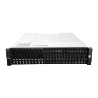
Table 25. ME4 Series enclosure models
ME4 Series: 4–port controller enclosure matrix - 2U
2.5" (SFF) 24-drive controller enclosures
Model Description Form Description Form
ME4024 Fibre Channel (16Gb/s) SFP
1,3
2U24 Fibre Channel (16Gb/s) SFP
1,3
2U12
ME4024 Internet SCSI (10GbE) SFP
2,3
2U24 Internet SCSI (10GbE) SFP
2,3
2U12
ME4024 HD mini-SAS (12Gb/s)
4
2U24 HD mini-SAS (12Gb/s)
4
2U12
ME4024 iSCSI 10Gbase-T (10Gb/s or 1Gb/s)
5
2U24 iSCSI 10Gbase-T (10Gb/s or 1Gb/s)
5
2U12
1-This model uses a qualified FC SFP option within the CNC ports (used for host connection). When in FC mode, the SFPs must be a
qualified 16Gb fiber-optic option. A 16Gb/s SFP can run at 16Gb/s, 8Gb/s, 4Gb/s, or auto-negotiate its link speed.
2-This model uses a qualified 10GbE iSCSI option within the controller module CNC ports (used for host connection).
Module removal and replacement
41

 Loading...