3-CNC ports support same-type or mixed-type SFPs in combination.
4-This model uses SFF-8644 connectors and qualified cable options for host connection.
5-This model supports 10Gb/s or 1Gb/s speeds (used for iSCSI host connection).
Table 26. High-density ME4 Series enclosure models
High-density 4-port controller enclosure matrix–5U
ME4 Series (2.5"/3.5") 84-drive controller enclosures
Model Description Form
ME4084 Fibre Channel (16Gb/s) SFP
1,3
5U84
ME4084 Internet SCSI (10GbE) SFP
2,4
5U84
ME4084 HD mini-SAS (12Gb/s)
4
5U84
ME4084 iSCSI 10Gbase-T (10Gb/s or 1Gb/s)
5
5U84
1-This model uses a qualified FC SFP option within the CNC ports (used for host connection). When in FC mode, the SFPs must be a
qualified 16Gb fiber-optic option. A 16Gb/s SFP can run at 16Gb/s, 8Gb/s, 4Gb/s, or auto-negotiate its link speed.
2-This model uses a qualified 10GbE iSCSI option within the controller module CNC ports (used for host connection).
3-CNC ports support same-type or mixed-type SFPs in combination.
4-This model uses SFF-8644 connectors and qualified cable options for host connection.
5-This model supports 10Gb/s or 1Gb/s speeds (used for iSCSI host connection).
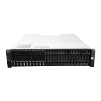
Attach or remove the 2U enclosure front bezel
The 2U12 controller enclosure in Attaching or removing the 2U enclosure front bezel is equipped with 2 controllers (4–port FC/ISCSI
model shown).
Figure 37. Attaching or removing the 2U enclosure front bezel
You can attach or remove the optional 2U enclosure bezel. Locate the bezel, and while grasping it with your hands, face the front panel of
the 2U12 or 2U24 enclosure. A partial view of a 2U12 enclosure is shown in
Attaching or removing the 2U enclosure front bezel.
1. Hook the right end of the bezel onto the right ear cover of the storage system.
2. Insert the left end of the bezel into the securing slot until the release latch snaps in place.
3. Secure the bezel with the keylock as shown in Attaching or removing the 2U enclosure front bezel.
To remove the bezel from the 2U enclosure, reverse the order of the preceding steps.
NOTE:
See Enclosure variants for details about various enclosure options.
42 Module removal and replacement

 Loading...