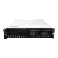
Figure 61. Removing a PCM (2 of 2)
NOTE: The remove PCM illustrations show a chassis configured as a 4-port FC/iSCSI controller enclosure. The
procedure applies to all 2U controller enclosures and expansion enclosures.
9. If replacing two PCMs, repeat steps 5 through 8.
Installing a PCM
Refer to Figure 60. Removing a PCM (1 of 2) and Figure 61. Removing a PCM (2 of 2) when performing this procedure, but ignore the
directional arrows—since you will insert the module into the slot rather than extract.
NOTE:
Handle the PCM carefully, and avoid damaging the connector pins. Do not install the PCM if any pins appear to
be bent.
1. Check for damage, especially to all module connectors.
2. With the PCM handle in the open position, slide the module into the enclosure, taking care to support the base and weight of the
module with both hands.
3. Cam the module home by manually closing the PCM handle. You should hear a click as the latch handle engages and secures the PCM
to its connector on the back of the midplane.
4. Connect the power cable to the power source and the PCM.
5. Secure the strain relief bales.
6. Using the management interfaces (the ME Storage Manager or CLI), verify whether the health of the new PCM is OK. Verify that the
green PCM OK LED is on/blinking per Table 11. PCM LED states. Verify that cooling fans are spinning with no fail states. Verify that
Ops panel states show no amber module faults.
7. If replacing two PCMs, repeat steps 1 through 5.
Completing the component installation process
This section provides a procedure for ensuring that the components installed in the replacement controller enclosure chassis function
properly.
1. Reconnect data cables between devices, as needed, to return to the original cabling configuration:
• Between cascaded storage enclosures.
• Between the controller and peripheral or SAN devices.
• Between the controller enclosure and the host.
2. Reconnect power cables to the storage enclosures.
Verifying component operation
1. Restart system devices by moving the power switch on the power supply to the On position in the following sequence:
a) Expansion enclosures first.
b) Controller enclosure next.
62
Module removal and replacement

 Loading...