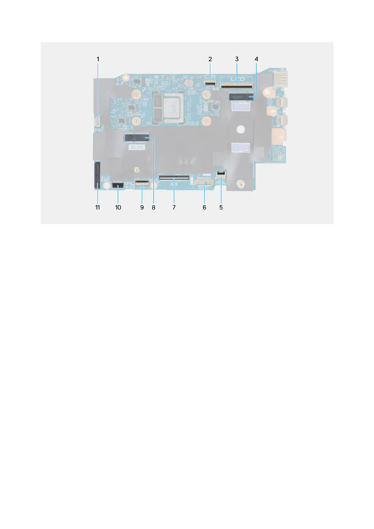
Figure 43. System board callouts
1. Fan cable connector (FAN)
2. Infrared camera cable connector (CIR)
3. Display-assembly cable connector (LCD)
4. M.2 solid state drive slot
5. Keyboard-backlight cable connector (KBBL)
6. Battery cable connector (BATT)
7. Keyboard cable connector (KB)
8. M.2 wireless-card slot (WLAN)
9. Touchpad cable connector (TP)
10. Speaker cables connector (SPK)
11. I/O board-cable connector (IOBD)
The following images indicate the location of the system board and provide a visual representation of the installation procedure.
Removing and installing Field Replaceable Units (FRUs)
67