Installing the system board
Prerequisites
If you are replacing a component, remove the existing component before performing the installation process.
About this task
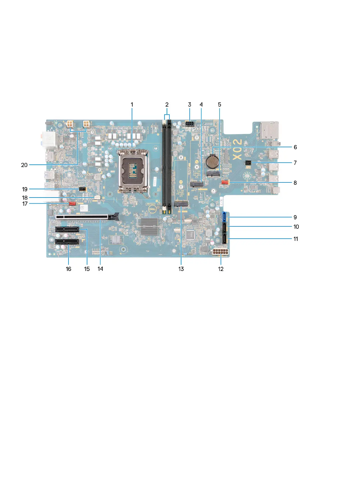
The following image indicates the slots and connectors on your system board.
1. Processor socket
2. U-DIMM slots
From the left (a>b>c>d):
a. DIMM 1
b. DIMM 2
3. SATA power cable
4. M.2 2230/2280 solid-state drive slot
5. M.2 2230 wireless-card slot
6. Coin-cell battery socket
7. Power-button cable
8. Front chassis-fan cable
9. Hard-drive data cable (SATA 0)
10. Hard-drive data cable (SATA 1)
11. Hard-drive data cable (SATA 2)
12. System-board power cable
13. M.2 2230/2280 solid-state drive slot
14. PCIe x16 slot (SLOT 1)
15. PCIe x4 slot (SLOT 2)
16. PCIe x4 slot (SLOT 3)
17. Back chassis-fan cable
18. Processor fan and heat-sink fan cable
19. Processor liquid cooler pump cable
Removing and installing components
59