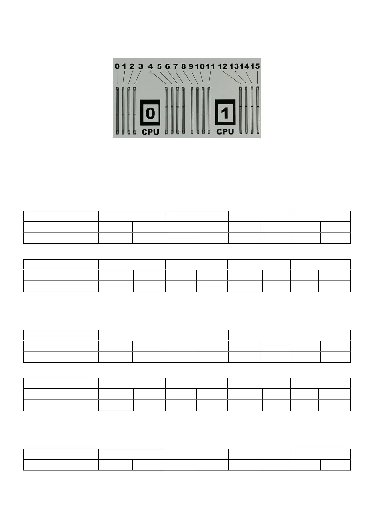
The following figure shows the layout of the CPUs and DIMMs inside the chassis. The front of the system is at the top of the
f
igure.
Figure 5. CPU and memory locations
To ensure maximum memory performance, there are memory DIMM population rules so that the memory loading and interleaving
is optimal. The sections below specifiy the DIMM location rules for each memory configurations:
DD6300 AIO Base (48 GB)
Table 5. Memory locations - CPU 0
Channel A Channel B Channel D Channel C
Slot 0 1 2 3 4 5 6 7
DD6300 AIO Base 8GB 8GB 8GB
Table 6. Memory locations - CPU 1
Channel A Channel B Channel D Channel C
Slot 8 9 10 11 12 13 14 15
DD6300 AIO Base 8GB 8GB 8GB
DD6300 AIO Expanded (96 GB)
Table 7. Memory locations - CPU 0
Channel A Channel B Channel D Channel C
Slot 0 1 2 3 4 5 6 7
DD6300 AIO Expanded 8GB 8GB 8GB 8GB 8GB 8GB
Table 8. Memory locations - CPU 1
Channel A Channel B Channel D Channel C
Slot 8 9 10 11 12 13 14 15
DD6300 AIO Expanded 8GB 8GB 8GB 8GB 8GB 8GB
DD6800 DLH (192 GB)
Table 9. Memory locations - CPU 0
Channel A Channel B Channel D Channel C
Slot 0 1 2 3 4 5 6 7
28 Field Replaceable Units