3. R
econnect the data cables to the same ports where they were connected on the original storage processor.
4. Reconnect the power cables to power the system back on.
Verify the fans
Steps
1. Enter the enclosure show fans command to check the status of the enclosure fans.
# e
nclosure show fans 1
Enclosure Description Level Status
--------- ----------- ------ ------
1 FAN 0A medium OK
FAN 0B medium OK
FAN 1A medium OK
FAN 1B medium OK
FAN 2A medium OK
FAN 2B medium OK
FAN 3A medium OK
FAN 3B medium OK
FAN 4A medium OK
FAN 4B medium OK
FAN 5A medium OK
FAN 5B medium OK
--------- ----------- ------ ------
Check the Status column to confirm that all of the fans in Enclosure 1 are OK.
2. Enter the alerts show current command and confirm that the system has cleared the alert for the failed fan. It may
take one to two minutes after the fan replacement before the system clears the alert.
# a
lerts show current
No active alerts.
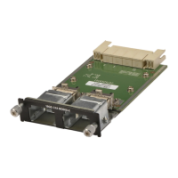
Verify the I/O module replacement
Check each I/O module LED. Each I/O module ejector handle contains a bi-colored LED. Green indicates normal function, while
an amber color indicates a fault condition.
Steps
Enter the alerts show current command and confirm that the system has cleared the alert for the failed I/O module. It
may take one to two minutes after the I/O module replacement before the system clears the alert.
# a
lerts show current
No active alerts.
Field Replaceable Units 41