CAUTION:
If it is necessary to replace both the chassis and the SP module, do not replace at the same time.
Important configuration information can be lost. In this instance, you must do a serial swap in which the SP
module is replaced first, the system is booted, the system is brought down, and then the chassis is replaced.
Shut down and disconnect the system
Steps
1. Stop the system using the system poweroff command to allow the proper shut down of the file system and other system
components.
NOTE:
The system poweroff command completes when the front panel blue LED turns off.
For help connecting to a system using a laptop computer and terminal emulator, see the document F
E Toolkit Inventory and
Common Procedures for FRU Tasks at https://support.emc.com.
2. Label each of the cables as to their connection location. Taking a photograph for reference is also helpful for re-connecting
the cables.
3. Disengage the wire clips, then disconnect both AC power cords from the rear of the system.
Powering off an unresponsive system
Follow these instructions if it is not possible to power off the system using the system poweroff command, for example, if
the system becomes unresponsive.
Steps
1. Locate the recessed power button on the back of the management panel, indicated by two facing triangles.
2. Using a ballpoint pen or the end of a paperclip, press and hold the button for ten seconds.
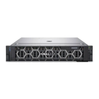
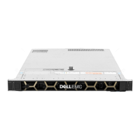
Chassis replacement
This procedure describes how to replace a chassis.
Steps
1. Remove the CMA, if applicable.
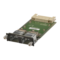
2. Remove the SP.
3. Loosen the two captive screws that attach the node to the front of the cabinet.
4. Pull the chassis from the cabinet and move it to the work area.
5. Install the SP into the chassis.
6. Remove the disk drives from the current chassis and install them into the new chassis.
7. Move the serial number pull-out tag as follows:
a. Grasp the edge of the serial number pull-out tag, located in the upper left hand front of the current chassis.
b. Pull out on the tag. Some force may be needed to remove the tag.
c. Insert the tag into the new chassis.
8. Install the chassis into the cabinet as follows:
a. From the front of the cabinet, align the rear of the chassis with the lip of each installed rail.
b. Carefully slide the chassis all the way into the cabinet.
c. Attach the chassis to the cabinet using two screws.
9. If applicable, install the CMA.
10. Reconnect the cables.
Field Replaceable Units 57