Figure 68. Aligning pin 1 marks of processor with tray
4. Lift the processor away from the carrier and place it into the processor tray. Ensure pin1 marks are aligned.
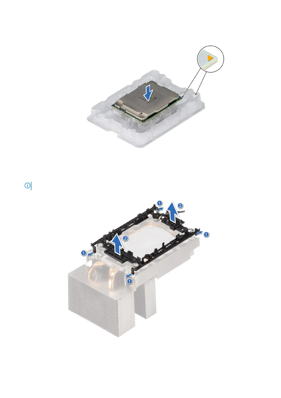
5. Flex the outer edges of the bracket to release the bracket from the processor.
NOTE: Ensure that the processor is placed in the processor tray after you remove it from the heat sink.
Figure 69. Removing the processor carrier
Installing and removing system components
75