EasyManuals Logo

Dell Force10 MXL Blade Getting Started Guide

Dell Force10 MXL Blade
38 pages
To Next Page IconTo Next Page
To Previous Page IconTo Previous Page
Page #25 background imageLoading...
Page #25 background image
Assembling a Switch Stack 25
Assembling a Switch Stack
After you complete the initial switch configuration, the MXL 10/40GbE
Switch is powered up and operational. Stacking is supported on the 40GbE
ports on the base module or a 2-Port 40GbE QSFP+ module to connect up
to six MXL 10/40GbE Switches in a single stack.
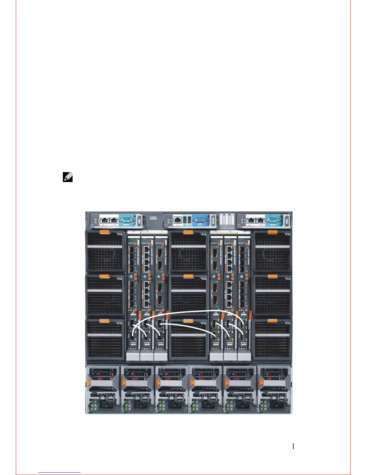
Figure 1-9 shows an example using six MXL 10/40GbE Switches in a chassis.
The MXL 10/40GbE Switches are connected to operate as a single stack in a
ring topology using only the 40GbE ports on the base modules. You can use
the 40GbE ports on the base module and plug-in modules to create a stack in
either a ring or daisy-chain topology.
NOTE: All MXL 10/40GbE Switches in the stack should be powered up with the
initial configuration before you attach the cables.
Figure 1-9. Six Stacked MXL 10/40GbE Switches

Other manuals for Dell Force10 MXL Blade

Questions and Answers:

Question and Answer IconNeed help?

Do you have a question about the Dell Force10 MXL Blade and is the answer not in the manual?

Dell Force10 MXL Blade Specifications

General IconGeneral
Switching Capacity1.28 Tbps
Forwarding Rate952 Mpps
Product TypeBlade Switch
Latency< 3 microseconds
Operating Temperature0°C to 40°C (32°F to 104°F)
RedundancyYes
ManagementCLI, SNMP, Web
Layer SupportLayer 2, Layer 3
Jumbo Frame SupportUp to 9216 bytes
Management Ports1 x 10/100/1000 Mbps
Storage Temperature-40°C to 70°C
Weight4.5 kg (9.9 lbs)

Related product manuals