4. Remove the keyboard.
5. Remove the base cover.
6. Remove the fan.
7. Remove the heat-sink (UMA).
8. Remove the RF switch board.
9. Remove the WLAN card.
10. Remove the WWAN card.
11. Remove the dock I/O board.
12. Remove the rear I/O board.
About this task
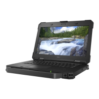
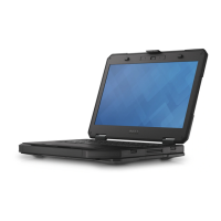
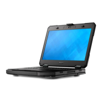
The following images indicate the location of the right Type-C daughterboard and provide a visual representation of the removal
procedure.
Steps
1. Remove the (M2x5) screw that secures the flat printed cable holder to the right Type-C daughterboard.
2. Disconnect the flat printed cable from its connector on the right Type-C daughterboard.
3. Disconnect the flat printed cable from its connector on the right Type-C daughterboard.
4. Remove the four (M2x3.5) screws that secure the right Type-C daughterboard to the system chassis.
5. Lift the right Type-C daughterboard from the system chassis.
64
Removing and installing components

 Loading...