System board layout
1. PCI-e x16 connector (slot 2) 2. PCI-e x1 Connector (slot 1)
3. VGA daughter board connector 4. Processor connector (CPU)
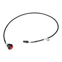
5. CPU power connector (ATX_CPU) 6. Intrusion switch connector
7. CPU fan connector 8. Memory module connectors
9. M.2 Slot 3 connector 10. Power switch connector
11. SD Media card reader connector 12. SATA 0 connector
13. ATX power connector 14. HDD and ODD power cable connector
15. Service mode jumper 16. Clear password jumper
17. Clear CMOS jumper 18. Speaker connector
19. SATA 1 connector 20. Coin cell battery
System board jumper
The service system board jumper must be set to Password to function normally. As long as the jumper stays at Service Mode,
all values set in the BIOS will not be saved and the system will not exit the manufacturing mode with an error prompt indicating
that jumpers are incorrect.
Removing and installing components
33