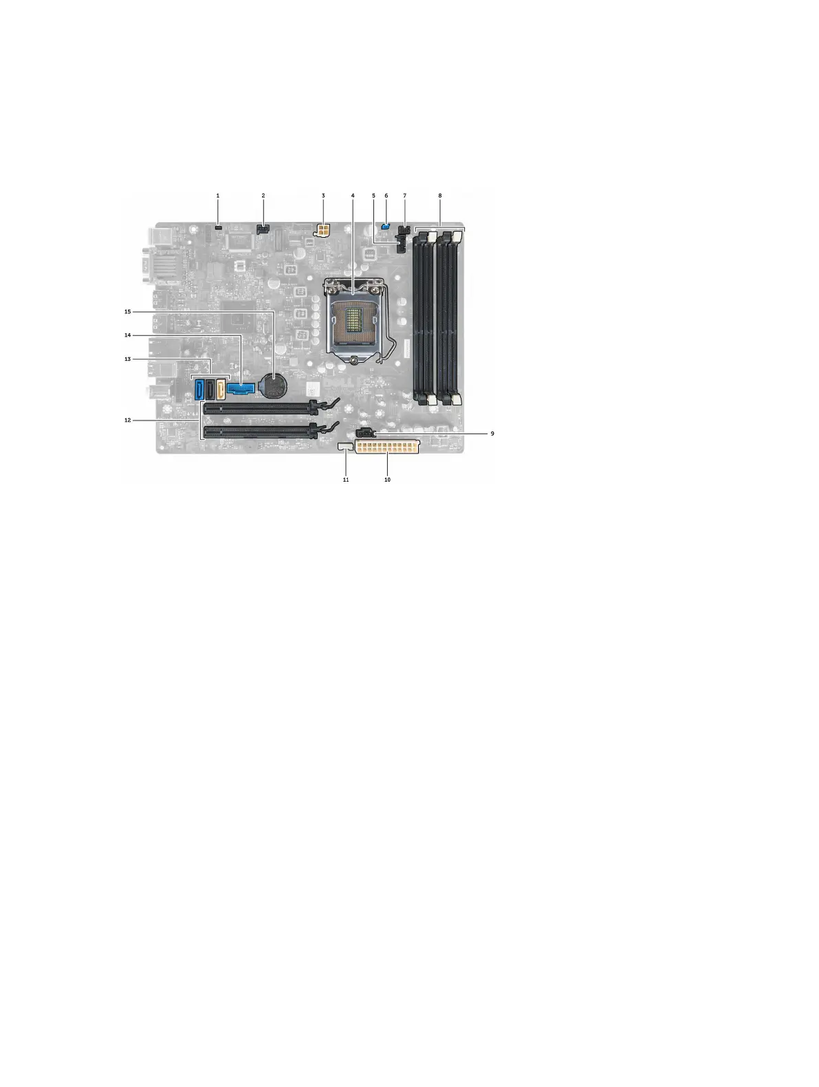
System Board Components
The following image displays the system board layout.
1. RTC reset jumper 2. intrusion-switch connector
3. power connector 4. processor
5. system fan connector 6. password jumper
7. power switch connector 8. memory module connectors
9. system fan connector 10. system power connector
11. internal speaker connector 12. PCI Express x16 connectors
13. SATA connectors 14. front-USB connector
15. coin-cell battery
Installing the System Board
1. Align the system board to the port connectors at the rear of the chassis and place the system board in the chassis.
2. Tighten the screws that secure the system board to the chassis.
3. Tighten the hex screw clockwise.
4. Re-connect all the cables to the system board.
5. Install the:
a. heat sink
b. expansion card
c. drive cage
d. front bezel
e. cover
38