Chapter 8 Servo Parameters
Revision January 2011 8-27
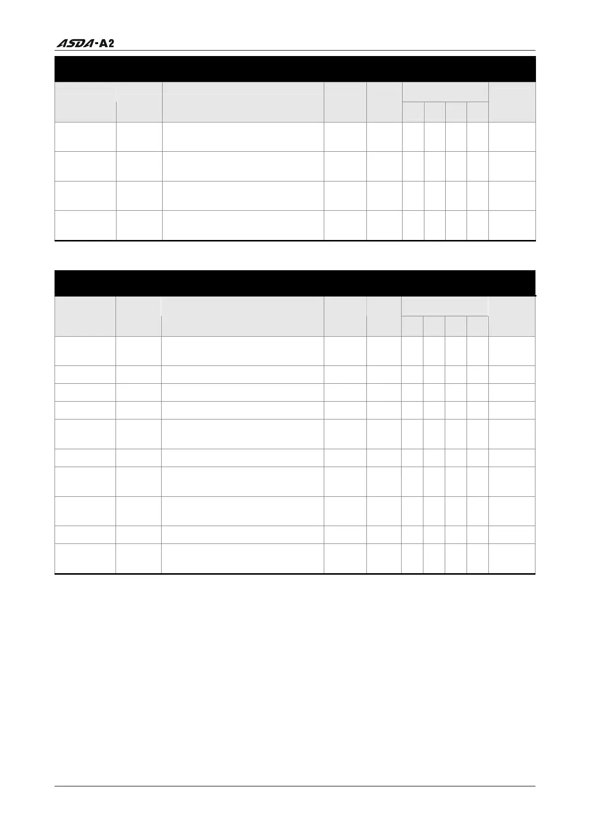
Digital I/O and Relative Input Output Setting
Control Mode
Parameter Name Function Default
Unit
PT PR S T
Related
Section
P1-43 MBT2
OFF Delay Time of
Elec
tromagnetic Brake
0 ms O
O O O 6.5.5
P1-47 SCPD Speed Reached Output Range 10 r/min
O
Table
8.B
P1-54 PER Positioning Completed Width 12800
pulse
O
O
Table
8.B
P1-56 OVW Output Overload Warning Time
120 % O
O O O
Table
8.B
Communication
Control Mode
Parameter Name Function Default
Unit
PT PR S T
Related
Section
P3-00
ADR
Communication Address
Setting
0x7F N/
A
O
O O O 9.2
P3-01 BRT
Transmission Speed
0x02
03
bps
O
O O O 9.2
P3-02 PTL
Communication Protocol
6 N/A
O
O O O
9.2
P3-03 FLT
Transmission Fault Treatment
0 N/A
O
O O O
9.2
P3-04 CWD
Communication Time Out
Detection
0 sec
O
O O O
9.2
P3-05 CMM
Communication Selection
0 N/A
O
O O O
9.2
P3-06
SDI
Digital Input Communication
Funct
ion
0 N/A
O
O O O 9.2
P3-07 CDT
Communication Response
Dela
y Time
0 1ms
O
O O O 9.2
P3-08
MNS
Monitor Mode
0000
N/A
O
O O O 9.2
P3-09 SYC
CANopen Synchronization
Setting
0x57A
1
N/A
O
O O O 9.2
Explanation of symbols (marked after parameter)
(
★) Read-only register.
(
▲) Parameter cannot be set when Servo On (when the servo drive is enabled).
(
) Parameter is effective only after the servo drive is restarted (after switching power off and
on).
(
) Parameter setting values are not retained when power is off.
Call 1(800)985-6929 for Sales
Call 1(800)985-6929 for Sales