Wiring Instructions
Installation Manual 48
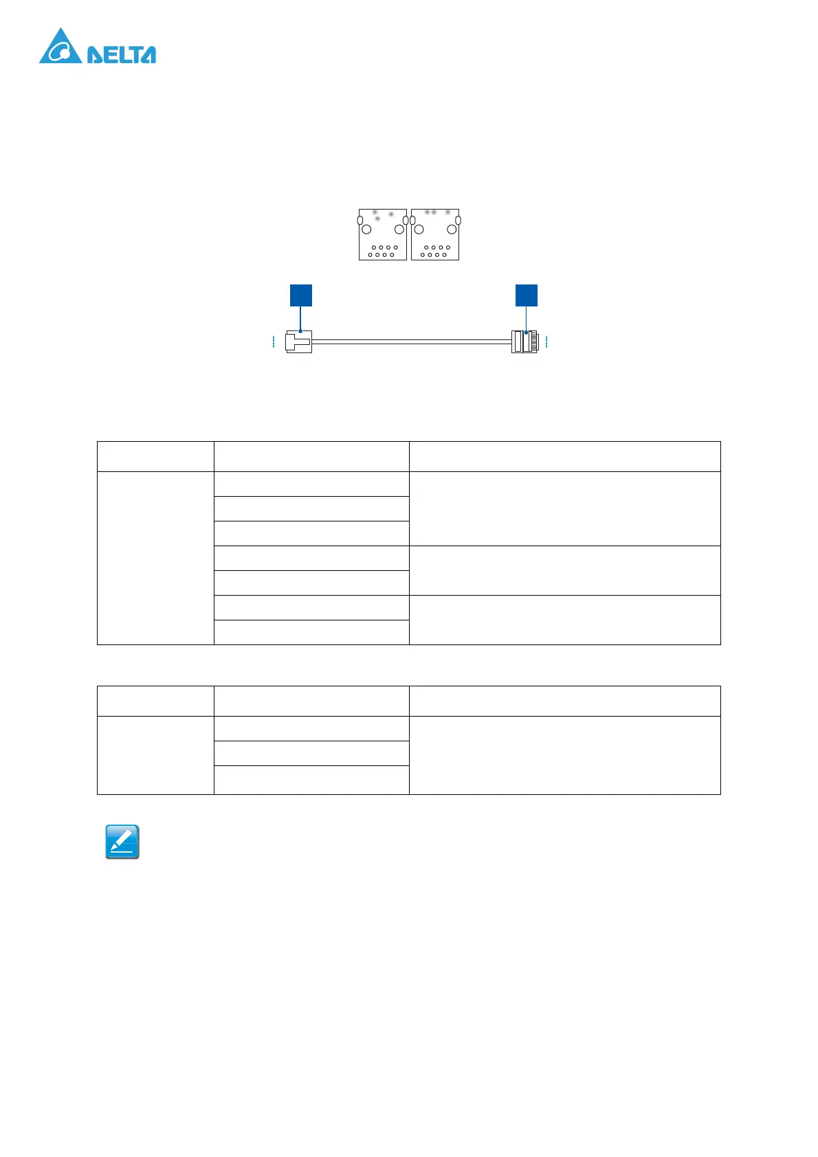
Communication Connector (CNJ11, CNJ12)
The CNJ11 and CNJ12 connectors are for communication with ESS controller or with other PCS in
parallel operation. Prepare two RJ45 connectors and six 1.32 mm
2
wires for each, and connect the
wires to the pin 1~2 and pin 4~7 of the RJ45 connector as the graphic and pin assignment below:
Figure 48. CNJ11, CNJ12 Pin Assignment
Table 9: CNJ11, CNJ12 Pin Assignment
Item Pin Assignment Notes
CNJ11, CNJ12
1: RS485-A2
For ESS Controller2: RS485-B2
3: NC
5: CAN-H2
For PCS parallel
6: CAN-L2
7: CAN-H3
For voltage detection
8: CAN-L3
Table 10: Used for Upper Controller (Use 3-pin)
Item Pin Assignment Notes
CNJ7
1: RS485A2 The same RS485 terminal as pin1 and pin2 of
CNJ11/CNJ12, for ESS Controller/Site Controller/
Local Controller/PC.
Used for installation when only one PCS.
2: RS485B2
3: NA
CNJ11 and CNJ12 are used for parallel operation more than one PCS. When multiple PCSs
are parallel operated, the network cable should be connected hand by hand, with CNJ11 or
CNJ12 of the first PCS is connected to upper controller and the terminal resistors should be
inserted to CNJ11 or CNJ12 of the last one.
PIN 1
PIN 8
PIN 1
PIN 8
P1 P2