10
ADJUSTING 90 AND 45 DEGREE
BEVEL STOPS
1. DISCONNECT THE MACHINE FROM THE POWER
SOURCE.
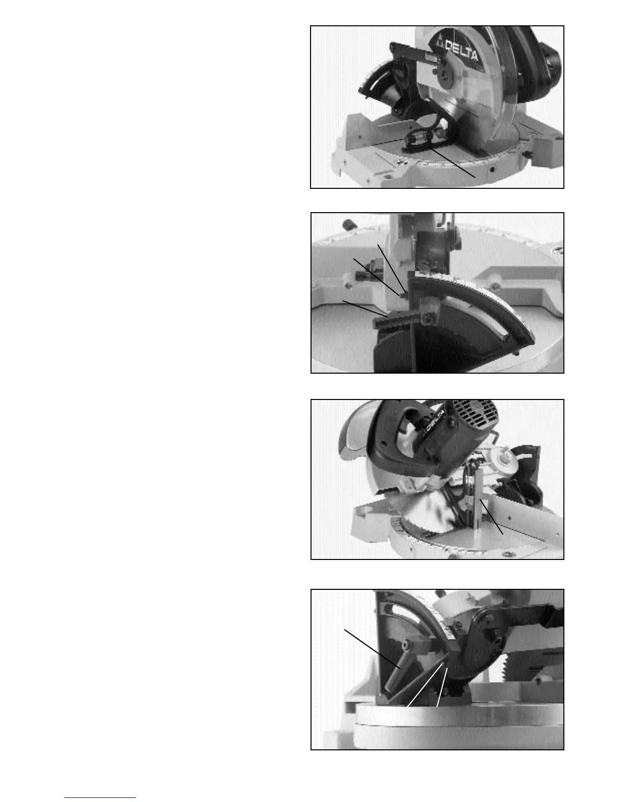
2. Move the cutting arm to the 90 degree bevel stop
position, as shown in Fig. 21, and tighten the bevel lock
handle.
3. Using a square (A) Fig. 21, place one end of the
square on the table and the other end against the blade.
Check to see if the blade is at 90 degrees to the table,
as shown.
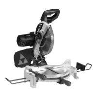
4. If an adjustment is necessary, loosen bevel lock han-
dle (B) Fig. 22, and tilt cutting arm until the blade is at 90
degrees to the table. NOTE: It may be necessary to
loosen locknut (C) and set screw (D) to accomplish this.
Then tighten bevel lock handle (B).
5. Loosen nut (C) Fig. 22, and tighten set screw (D) until
it bottoms. Then tighten locknut (C).
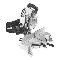
6. Tilt the cutting arm all the way to the left miter posi-
tion and tighten the bevel lock handle.
7. Using a combination square (A) Fig. 23, check to see
if the blade is at 45 degrees to the table, as shown.
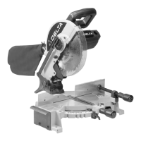
8. If an adjustment is necessary, loosen bevel lock han-
dle (B) Fig. 24, and tilt the cutting arm until the blade is
at 45 degrees to the table. NOTE: It may be necessary
to loosen locknut (E) and set screw (F) to accomplish
this. Then tighten bevel lock handle (B).
9. Loosen locknut (E) Fig. 24, and tighten set screw (F)
until it bottoms. Then tighten locknut (E).
10. These positive stops enable you to rapidly position
the blade at the 90 and 45 degree bevel positions.
Fig. 21
Fig. 22
A
B
C
Fig. 23
A
Fig. 24
B
E
F
D