Chapter 8 Parameters ASDA-A2
8-140 Revision February, 2017
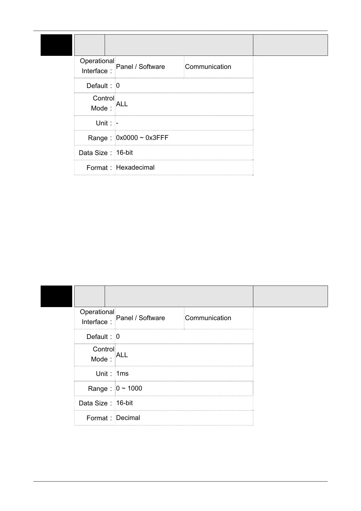
P3-06■
SDI Control Switch of Digital Input (DI)
Address: 030CH
030DH
Operational
Interface:
Panel / Software Communication
Related Section:
9.2
Default:
0
Control
Mode:
ALL
Unit:
-
Range:
0x0000 ~ 0x3FFF
Data Size:
16-bit
Format:
Hexadecimal
Settings:
The source of DI controls the switch.
Each bit of this parameter decides one input source of DI signal:
Bit0 ~ Bit7 correspond to DI1 ~ DI8.
Bit8 ~ Bit13 correspond to extended DI EDI9 ~ EDI14;
The setting of bit is as the followings:
0: The input status is controlled by the external hardware.
1: The input status is controlled by P4-07.
For the functional planning of digital input, please refer to:
DI1 ~ DI8: P2-10 ~ P2-17
EDI9 ~ EDI14: P2-36 ~ P2-41
P3-07 CDT Communication Response Delay Time
Address: 030EH
030FH
Operational
Interface:
Panel / Software Communication
Related Section:
9.2
Default:
0
Control
Mode:
ALL
Unit:
1ms
Range:
0 ~ 1000
Data Size:
16-bit
Format:
Decimal
Settings:
Delay the time of communication response from servo drive to
controller

 Loading...