ASDA-A2 Chapter 3 Wiring
Revision February, 2017 3-35
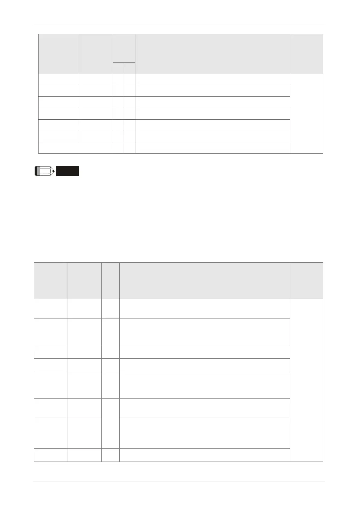
DO Signal
Name
Operation
Mode
Pin
No.
Details
Wiring
Method
(Refer to
3.4.3)
+ -
SDO_9 ALL - - Output the status of bit09 of P4-06
C5/C6/C7/
C8
SDO_A ALL - - Output the status of bit10 of P4-06
SDO_B ALL - - Output the status of bit11 of P4-06
SDO_C ALL - - Output the status of bit12 of P4-06
SDO_D ALL - - Output the status of bit13 of P4-06
SDO_E ALL - - Output the status of bit14 of P4-06
SDO_F ALL - - Output the status of bit15 of P4-06
NOTE
1) For example, if the user selects PR mode, pin 3 and 2 are HOME. If the user selects S mode,
pin 3 and 2 are TSPD.
2) The unlisted Pin No means the signal is not the preset one. If users want to use it, parameters
need to be changed and set as the desired ones. Please refer to Section 3.4.4 for further
details.
The explanation of DI signal default setting is as the followings
DI Signal
Name
Operation
Mode
Pin
No.
Function
Wiring
Method
(Refer to
3.4.3)
SON ALL 9
When DI is ON, the servo circuit will be activated and the
motor coil will generate current.
C9/C10/C
11
/C12
ARST ALL 33
When the alarm (ALRM) occurs, this signal is used to
reset the servo drive and output the signal, Ready
(SRDY) again.
GAINUP ALL -
It is for switching the controller gain.
CCLR PT, PR 10
It is for clearing the deviation counter.
ZCLAMP ALL -
When this DI is ON and the motor speed is slower than
the setting of P1-38, the motor position will be locked
when the signal is triggered.
CMDINV PR, T, S -
When this DI is ON, the motor will operate in the opposite
direction.
CTRG
PR,
PR-S,
PR-T
10
In PR mode, the moment CTRG is ON (rising edge), save
the position command selected by POS0~2 into the
controller and then trigger the command.
TRQLM S, Sz 10
ON means the torque limit command is effective.

 Loading...