Delta Din-rail Power Meter DPM- D510 User Manual
3- 8
3.3 Wiring
3.3.1
Wiring Diagrams
To avoid electric shock, do not change the wiring when the power is on.
Install a breaker switch on the power cord for the meter because there is no power switch on the power
meter.
When the measured voltage is higher than the rated specification for the device, it is necessary to use an
external potential transformer (PT).
When the measured current is higher than the rated specification for the device, it is necessary to use an
external current transformer (CT).
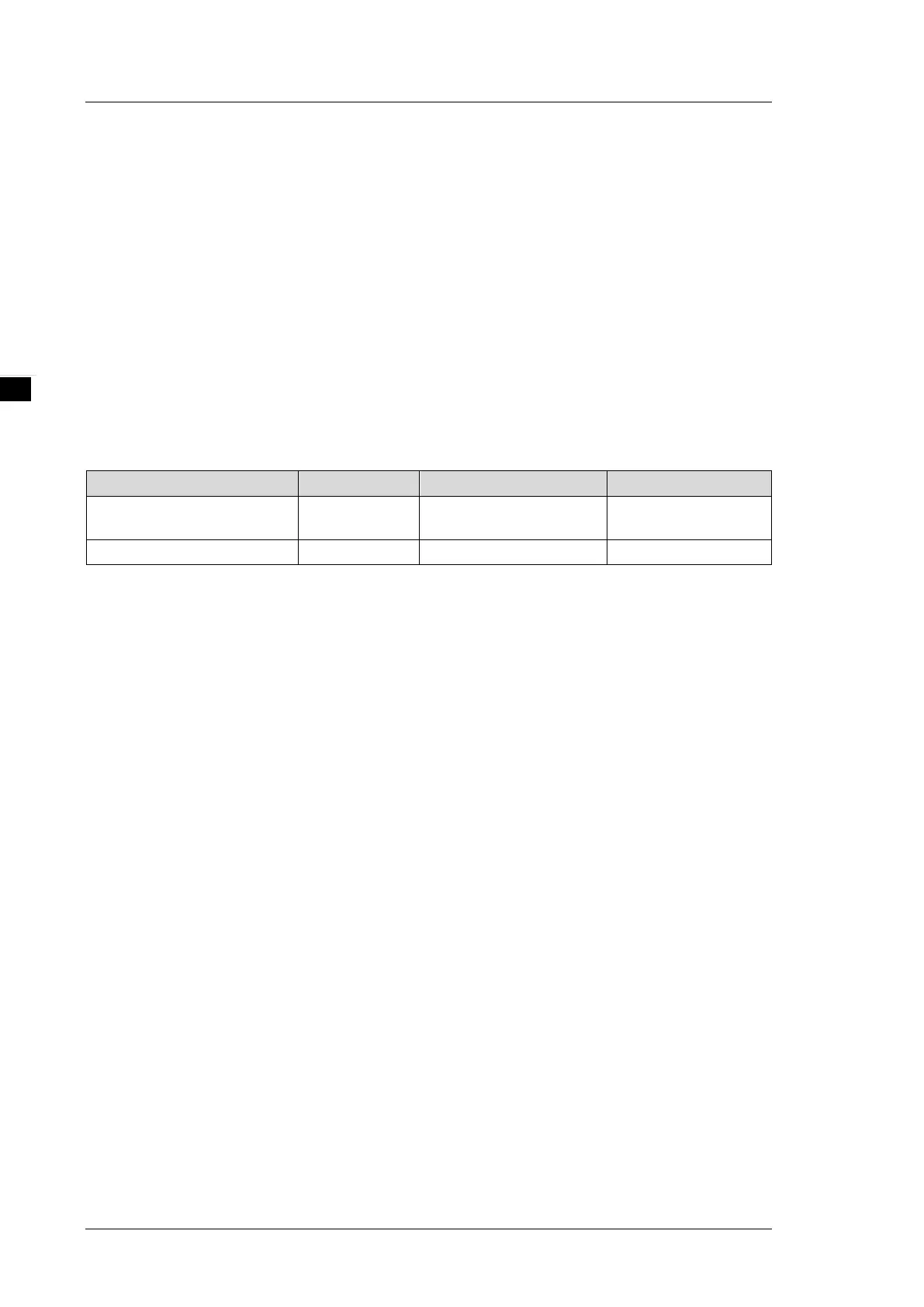
The following table shows the recommended wiring materials.
Connecting Terminals Wire Diameters Screw Turning Torque Wire heat resistance
Operating Power/ Voltage
Measurement
AWG 10–22 5.0 kgf-cm (0.5 N·m) > 70°C
Current Measurement/ RS-485 AWG 10–22 5.0 kgf-cm (0.5 N·m) > 70°C