1 Analog Input Module DVP04AD-E2
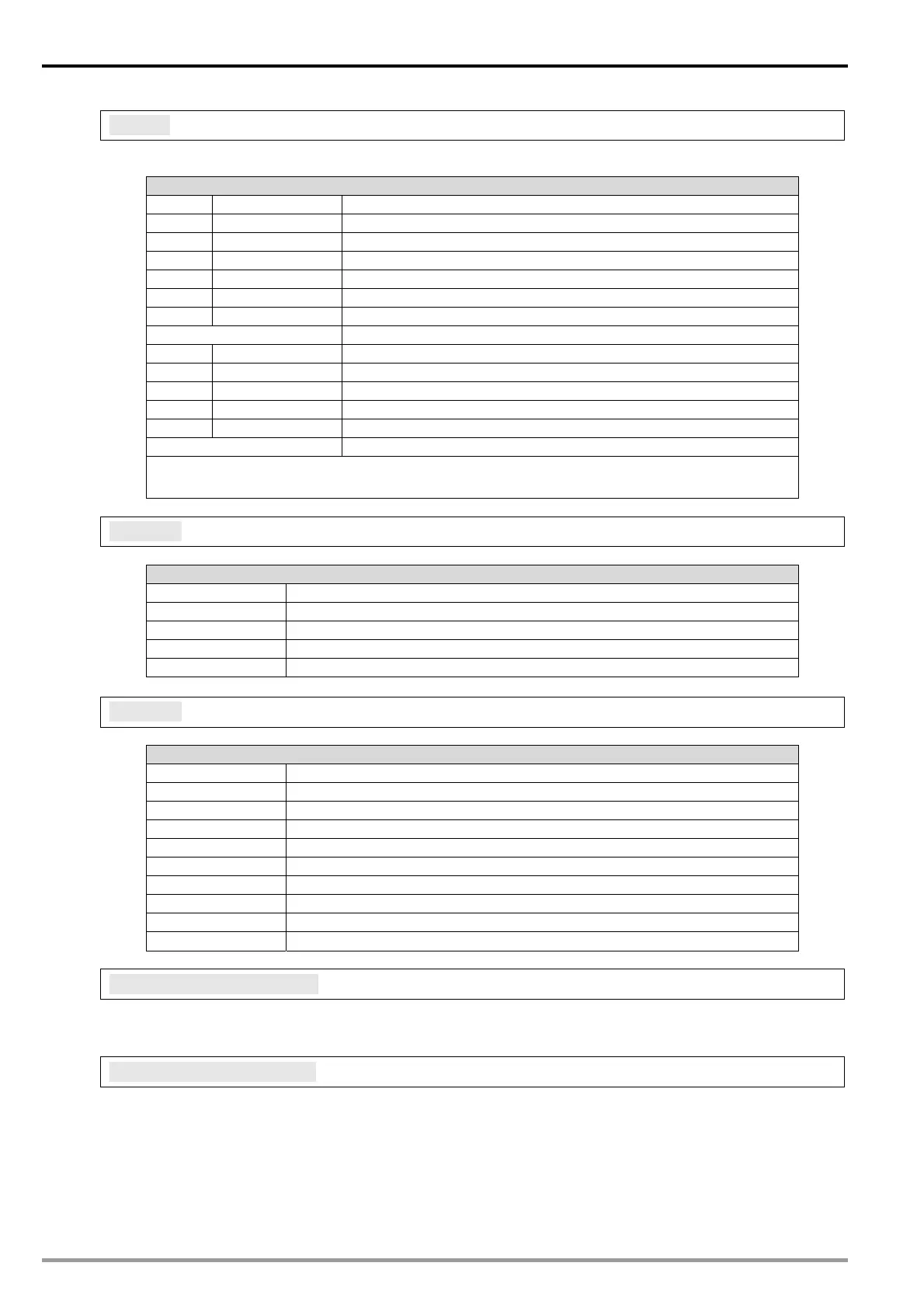
CR#43: Error status. Default=H’0000
[Explanation]
CR#43: error status value. See the table below:
Description
bit0 K1 (H’1) Power supply error
bit1 K2 (H’2) Hardware error
bit2 K4 (H’4) Upper / lower bound error
bit3 K8 (H’8) CH1 Conversion error
bit4 K16 (H’10) CH2 Conversion error
bit5 K32 (H’20) CH3 Conversion error
bit6 K64 (H’40) CH4 Conversion error
bit7 ~ bit8 Reserved
bit9 K512(H’0200) Mode setting error
bit10 K1024(H’0400) Average times error
bit11 K2048(H’0800) Upper / lower bound setting error
bit12 K4096(H’1000) Set value changing prohibited
bit13 K8192(H’2000) Communication breakdown on next module
bit14 ~ bit15 Reserved
Note: Each error status is determined by the corresponding bit (b0 ~ b13) and there may be more
than 2 errors occurring at the same time. 0 = normal; 1 = error
CR#100: Function: Enable/Disable limit detection
[Explanation]
Description
bit0=1 Enable CH1 limit detection
bit1=1 Enable CH2 limit detection
bit2=1 Enable CH3 limit detection
bit3=1 Enable CH4 limit detection
bit4 ~ bit15
Reserved
CR#101: Upper and lower bound status
[Explanation]
Description
bit0=1 CH1 exceeds lower bound
bit1=1 CH2 exceeds lower bound
bit2=1 CH3 exceeds lower bound
bit3=1 CH4 exceeds lower bound
bit4 ~ bit7
Reserved
bit8=1 CH1 exceeds upper bound
bit9=1 CH2 exceeds upper bound
bit10=1 CH3 exceeds upper bound
bit11=1 CH4 exceeds upper bound
bit12 ~ bit15
Reserved
CR#102, 103, 104, 105: Set value of CH1 ~ CH4 upper bound
[Explanation]
Set the upper bound value of CH1 ~ CH4. Default = K32,000
CR#108, 109, 110, 111: Set value of CH1 ~ CH4 lower bound
[Explanation]
Set the lower bound value of CH1 ~ CH4. Default = K-32,000
DVP-ES2 Module Manual
1-8

 Loading...


