2 Analog Output Module DVP02DA-E2/DVP04DA-E2
3. You can read the model name in the program to see if the extension module exists.
CR#1: Firmware version
[Explanation]
Display the current firmware version in hex, e.g. version V1.00 is indicated as H’0100.
CR#2, 3, 4, 5: CH1 ~ CH4 output mode setting
[Explanation]
Set the working mode of the channels in the analog output module. There are 4 modes for each channel
which can be set up separately.
When you set CH1 as mode 1 (H’0001) CR#2 has to be set as H’0001. The default setting = H’0000. Take
CH1 as example:
Mode 0 (H’0000): Voltage output (-10V ~ +10V).
Mode 1 (H’0001): Current output (0mA ~ 20mA).
Mode 2 (H’0002): Current output (4mA ~ 20mA).
Mode -1 (H’FFFF): CH1 unavailable.
CR#28, 29, 30, 31: Adjusted Offset value of CH1 ~ CH4
[Explanation]
1. Set the adjusted Offset value of CH1 ~ CH4, which represents the corresponding voltage (current)
output value when the digital input value = 0
2. Default setting = K0.
CR#34, 35, 36, 37: Adjusted Gain value of CH1 ~ CH4
[Explanation]
1. Set the adjusted Gain value of CH1 ~ CH4, which represents the corresponding voltage (current)
output value when the digital input value = 16,000.
2. Default setting = K16,000.
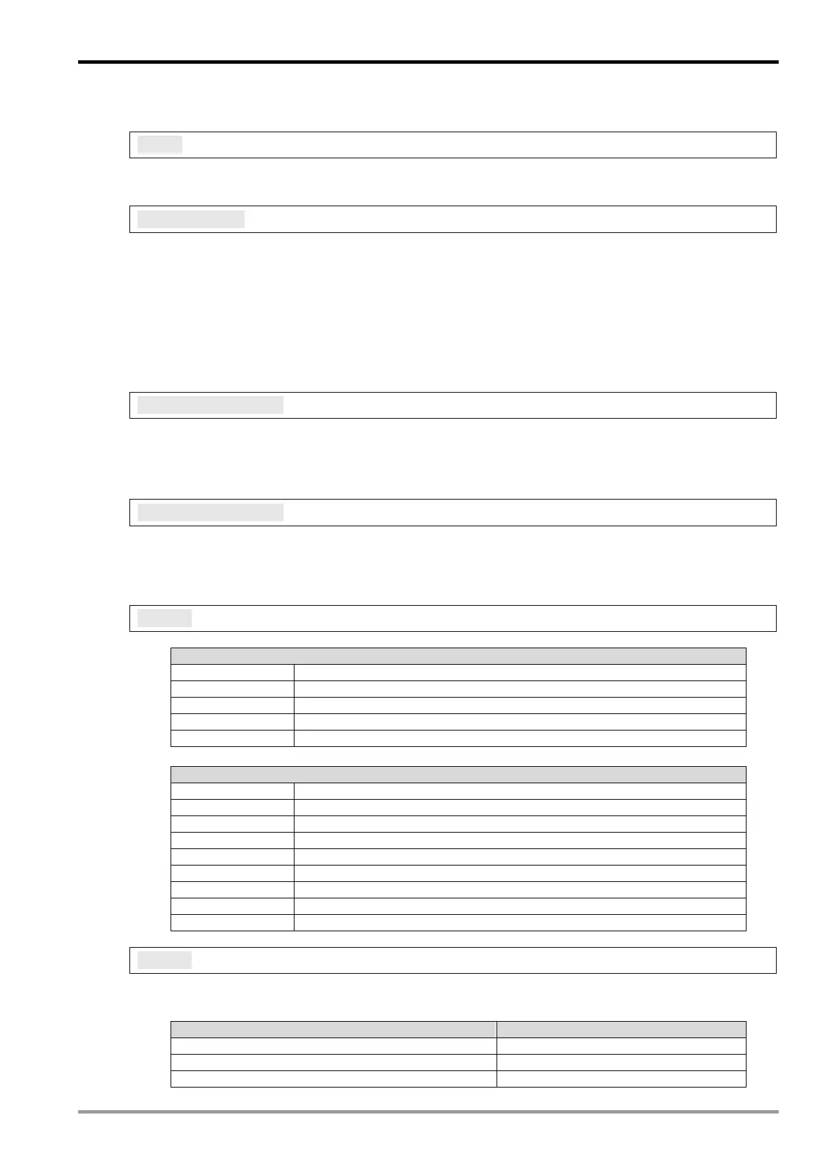
CR#40: Function: Set value changing prohibited, Default = H’0000
[Explanation]
Description
bit0 b0=0, CH1 changing allowed; b0=1, CH1 changing prohibited
bit1 b1=0, CH2 changing allowed; b1=1, CH2 changing prohibited
bit2 b2=0, CH3 changing allowed; b2=1, CH3 changing prohibited
bit3 b3=0, CH4 changing allowed; b3=1, CH4 changing prohibited
bit4 ~ bit15 Reserved
Relative
CR#2 ~ CR#5 Output mode setting of CH1 ~ CH4
CR#28 ~ CR#31 Adjusted Offset value of CH1 ~ CH4
CR#34 ~ CR#37 Adjusted Gain value of CH1 ~ CH4
CR#42 Return to default setting
CR#100 Function: Enable/Disable limit detection
CR#102~CR#105 Set value of CH1~CH4 upper bound
CR#108~CR#111 Set value of CH1~CH4 lower bound
CR#114~CR#117 Output update time of CH1 ~ CH4
CR#118 LV output mode setting
CR#41: Save all the set values, Default =H’0000
[Explanation]
Save function setting. Save all the set values to the internal flash memory. When saving is completed,
CR#41 will be set to H’FFFF.
Set value Function
H0 No action
HFFFF Saving completed
H5678 Saving enabled.
DVP-ES2 Module Manual
2-5

 Loading...


