3 Mixed Analog Input/Output Module DVP06XA-E2
4. Next, let’s
take 3.8.1 Speed tracing of AC motor drive
as example.
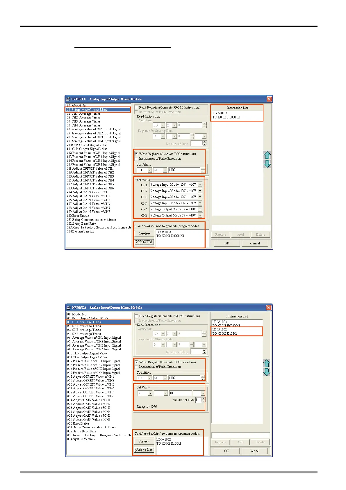
Step 1: Select “#1 Set up Input/Output Mode”.
Step 2: Check “Write Register” to generate TO instruction. Set the condition as “LD M1002”.
Step 3: Set CH1 ~ CH4 as “Voltage Input Mode -10V ~ +10V” and CH5 ~ CH6 as “Voltage Output Mode 0V ~
+10V”.
Step 4: Click “Preview” to check if the generated program codes are correct.
Step 5: Click “Add to List” to display the instruction codes in “Instruction List”. The setup of CR#1 is
completed.
5. Setting up CR#2 is similar to the setup of CR#1.
Step 1: Select “#2 CH1 Average Times”.
Step 2: Check “Write Register” to generate TO instruction. Set the condition as “LD M1002”.
Step 3: Set the set value as “K10” and number of data as “1”
Step 4: Click “Preview” to check if the generated program codes are correct.
Step 5: Click "Add to List” to display the instruction codes in “Instruction List". The setup of CR#2 is
completed.
Step1
Step2
Step3
Step4
Step5
6. The setup of other CR parameters can follow the steps illustrated above.
DVP-ES2 Module Manual
3-24

 Loading...


