4 Temperature Measurement Module DVP04PT-E2
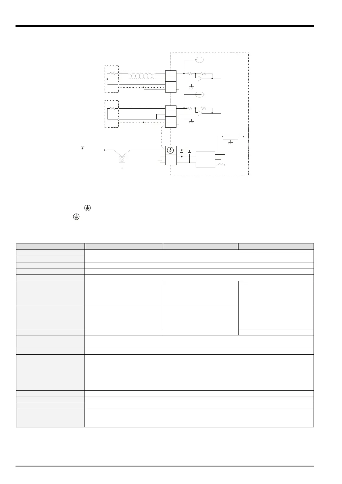
4.4 External Wiring
PT100/PT1000
CH1
1mA
DC/ DC
5V
AG
+15V
-15V
AG
AG
AG
0V
24V
FE
I1-
I1+
O1+
*2
*3
1mA
Shielded cable*1
Converter
System grounding
Class 3 Grounding (100 or less)Ω
Terminal of
power module
0~300Ω
CH4
FE
I4-
I4+
O4+
NI100/NI1000
*1: Wiring for analog input should adopt cables of PT100 / PT1000 temperature sensor or double shielded
cable and should be separated from other power cables that may cause interference. Please apply 3 wires
for PT100 / PT1000. If a 2 wires sensor is applied, please short-circuit I+ and I- terminals.
*2: Connect FE with
terminal for noise suppression.
*3: Connect the
terminal on both power module and DVP04PT-E2 to the system grounding point then
ground the point or connect it to the cover of power distribution cabinet.
4.5 Functions and Specifications
DVP04PT-E2 Celsius (°C) Fahrenheit (°F) Input Impedance
Power supply voltage 24V DC (20.4V DC ~ 28.8V DC) (-15% ~ +20%)
Connector European standard removable terminal block (Pin pitch: 5mm)
Analog input channel 4 channels
Applicable sensor type 3-WIRE PT100 / NI100 / PT1000 / NI1000, 0~300 input impedance
Current excitation 1.53mA(PT100/NI100), 200uA (PT1000/NI1000)
Range of input
PT100: -180°C ~ 800°C
NI100: -80°C ~ 170°C
PT1000: -180°C ~ 800°C
NI1000: -80°C ~ 170°C
PT100: -292°F ~ 1472°F
NI100: -112°F ~ 338°F
PT1000: -292°F ~ 1472°F
NI1000: -112°F ~ 338°F
0~300
Range of digital conversion
PT100: K-1,800 ~ K8,000
NI100: K-800 ~ K1,700
PT1000: K-1,800 ~ K8,000
NI1000: K-800 ~ K1,700
PT100: K-2920 ~ K14720
NI100: K-1120 ~ K3380
PT1000:K -2920~ K14720
NI1000: K-1120 ~ K3380
0~3000
Resolution 16 bits (0.1°C) 16 bits (0.18°F) 16 bits (0.1)
Overall accuracy
0.3% when in full scale (25°C, 77°F)
±0.6% when in full scale within the range of 0 ~ 55°C, 32 ~ 131°F
Response time 1.6 sec / all channels
Isolation
Optical coupler isolation between digital circuits and analog circuits. No isolation among analog
channels.
500VDC between digital circuits and Ground
500VDC between analog circuits and Ground
500VDC between analog circuits and digital circuits
500VDC between 24VDC and Ground
Digital data format 16 significant bits are available; in 2’s complement.
Average function Supported. Available for setting up average times in CR#8 ~ CR#11. Range: K1 ~ K100.
Self-diagnosis Upper and lower bound detection in all channels
Series connection to
DVP-PLC MPU
The modules are numbered from 0 to 7 automatically by their distance from MPU. No.0 is the
closest to MPU and No.7 is the furthest. Maximum 8 modules are allowed to connect to MPU and
will not occupy any digital I/O points.
DVP-ES2 Module Manual
-2

 Loading...


